
Technical data

13.0 Changing Components
39
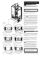
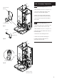
13.12 Pressure Gauge (Fig. 67)
1. Drain the boiler (see Section 13.1 paragraph 2 & 3).
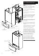
2. Undo the nut retaining the capillary in the
connection at the return pipe (Fig. 68).
3. Depress the two lugs on either side of the
pressure gauge and feed through the bracket.
4. Fit new pressure gauge and reassemble in
reverse order.
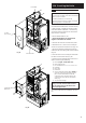
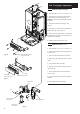
13.13 Pressure Relief Valve (Fig. 69)
1. The pressure relief valve is positioned on the
hydraulic manifold at the back of the pump.
2. Drain the boiler
(see Section 13.1 paragraph 2 & 3).
3. Disconnect the union between the valve and
the discharge pipe.
4. Slacken the screw retaining the valve.
5. Pull the valve upwards to disengage it.
6. Fit the new pressure relief valve and
reassemble in reverse order.
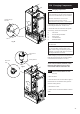
Fig. 67
Lug
Pressure Gauge
Pressure Gauge
Bracket
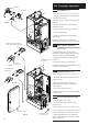
Fig. 68
Capillary
Return Pipe
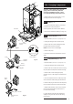
Fig. 69
Pressure Relief Valve
Expansion Vessel
removed for clarity