Installation & Servicing Instructions Baxi Combi 133 HE Plus Baxi Combi 100 HE Plus Baxi Combi 80 HE Plus Gas Fired Wall Mounted Condensing Combination Boiler These instructions include the Benchmark Commissioning Checklist and should be left with the user for safe keeping.
Natural Gas Baxi Combi 133 HE Plus G.C.No 47 075 14 Baxi Combi 100 HE Plus G.C.No 47 075 15 Baxi Combi 80 HE Plus G.C.No 47 075 16 Building Regulations and the Benchmark Commissioning Checklist Building Regulations (England & Wales) require notification of the installation of a heating appliance to the relevant Local Authority Building Control Department. From 1 April 2005 this can be achieved via a Competent Persons Self Certification Scheme as an option to notifying the Local Authority directly.
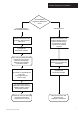
Installer Notification Guidelines Choose Building Regulations Notification Route Competent Person's Self Certification Scheme Building Control Install and Commission this appliance to manufacturer's instructions Contact your relevant Local Authority Building Control (LABC) who will arrange an inspection or contact a government approved inspector Complete the Benchmark Checklist If you notify via CORGI Scheme, CORGI will then notify the relevant Local Authority Building Control Scheme on member's beha
Legislation IMPORTANT - Installation, Commissioning, Service & Repair This appliance must be installed in accordance with the manufacturer’s instructions and the regulations in force. Read the instructions fully before installing or using the appliance. In GB, this must be carried out by a competent person as stated in the Gas Safety (Installation & Use) Regulations.
Contents Section © Baxi Heating UK Limited 2005 Page 1.0 Introduction 6 2.0 General Layout 7 3.0 Appliance Operation 8 4.0 Technical Data 9 5.0 Dimensions and Fixings 12 6.0 System Details 13 7.0 Site Requirements 16 8.0 Installation 22 9.0 Electrical 29 10.0 Commissioning the Boiler 31 11.0 Fitting the Outer Case 35 12.0 Servicing the Boiler 36 13.0 Changing Components 38 14.0 Short Parts List 49 15.0 Fault Finding 50 16.
1.0 Introduction This boiler is fitted with a flow switch interlock that prevents it from firing when the heating demand is satisfied. 1.1 Description 1. The Baxi Combi HE Plus Range are fully automatic gas fired wall mounted condensing combination boilers. They are room sealed and fan assisted, and will serve central heating and mains fed domestic hot water. 2. The boiler is preset to give a maximum output of 23.9 kW (81,500 Btu/h) for central heating and (39.0 kW (133,000 Btu/h) 133 model) (30.
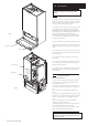
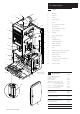
2.0 General Layout 2.1 1 2 3 22 Layout 1. Wallplate 2. Flue Elbow 3. Air Box 4. Heat Exchanger 5. Burner 6. Fan Protection Thermostat 7. Fan Assembly 8. DHW Plate Heat Exchanger 9. Three Way Valve 10. Facia Box 11. Water Pressure Gauge 12. Gas Tap 13. Circulation Pump 14. Pressure Relief Valve 15. Return Thermistor 16. Gas/Air Ratio Valve 17. PCB 18. Flow Temperature Safety Thermostat 19. Flow Temperature Thermistor 20. Manual Air Vent 21. Automatic Air Vent 22.
3.0 Appliance Operation NOTE: All delay timers mentioned in 3.1 and 3.2 are overridden by domestic hot water demand. 3.1 Central Heating Mode 1. With a demand for heating, the pump circulates water through the primary circuit. At a flow rate of approximately 4.5 l/min the central heating flow switch operates, initiating the ignition sequence. 2.
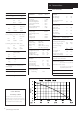
4.0 Technical Data 4.1 Appliance Type C13 Appliance Category CAT I 2H Heat Input Gross DHW Max kW 45.45 Btu/h 155,000 C33 Heat Input Gross CH Max Factory Set kW 33.7 26.95 Btu/h 115,000 92,000 Heat Output CH Non Condensing (70°C Mean Water temp) Max Factory Set kW 30.0 23.9 Btu/h 102,000 81,500 Condensing (40°C Mean Water temp) Max Factory Set kW 31.4 25.1 Btu/h 107,000 85,600 Max Gas Rate m3/h ft3/h (Natural Gas) (After 10 Mins) 4.2 148.
4.0 Technical Data 4.2 Appliance Type C13 Appliance Category CAT I 2H Heat Input Gross DHW Max kW 33.7 Btu/h 115,000 C33 Heat Input Gross CH Max Factory Set kW 33.7 26.95 Btu/h 115,000 92,000 Heat Output CH Non Condensing (70°C Mean Water temp) Max Factory Set kW 30.0 23.9 Btu/h 102,000 81,500 Condensing (40°C Mean Water temp) Max Factory Set kW 31.4 25.1 Btu/h 107,000 85,600 Max Gas Rate m3/h ft3/h (Natural Gas) (After 10 Mins) 3.1 110.
4.0 Technical Data 4.3 Appliance Type C13 Appliance Category CAT I 2H Heat Input Gross DHW Max kW 26.95 Btu/h 92,000 C33 Heat Input Gross CH Max kW 26.95 Btu/h 92,000 Heat Output CH Non Condensing (70°C Mean Water temp) Max kW 23.9 Btu/h 81,500 Condensing (40°C Mean Water temp) Max kW 25.1 Btu/h 85,600 Max Gas Rate m3/h ft3/h (Natural Gas) (After 10 Mins) 2.5 87.
5.0 Dimensions and Fixings E 3° (1 in 20) SIDE FLUE (left and right) For every 1m of horizontal flue length, the clearance above the top of the flue elbow should be 55mm to incorporate the 3° (1 in 20) fall in the flue from the terminal to the elbow. DIMENSIONS A 850mm B 320mm A C 490mm D 125mm Ø Min.
6.0 System Details 6.1 Information In GB it is necessary to comply with the Water Supply (Water Fittings) Regulations 1999 (or for Scotland, The Water Byelaws 2000, Scotland). The Baxi Combi 133, 100, 80 HE Plus Combination Boilers are an Approved Product under the Water Regulations. To comply with the Water Regulations your attention is drawn to The Water Regulations Advisory Service (WRAS) which gives full details of the requirements. In IE the requirements given in the current edition of I.S.
6.0 System Details 6.2 System Control 1. The boiler is designed for use in a heating system that incorporates external controls, i.e. a minimum of a timer device. Stop Valve Double Check Valve 2. Suitable timer kits are available as optional extras. Stop Valve 6.3 DHW Mains Inlet Temporary Hose System Filling and Pressurising (Fig. 3) 1.
6.0 System Details Other Tap Outlets 6.6 1. All DHW circuits, connections, fittings, etc. should be fully in accordance with relevant standards and water supply regulations. Boiler Expansion Vessel Domestic Hot Water Circuit 2.When installed in accordance with 1 above this appliance does not require a check valve to meet water supply regulations. However when the system includes any device which prevents water expanding back towards the supply, then an expansion vessel must be fitted (e.g.
7.0 Site Requirements 7.1 Location NOTE: Due to the high efficiency of the boiler a plume of water vapour will be discharged from the flue. This should be taken into account when siting the flue terminal. 1. The boiler may be fitted to any suitable non-flammable wall with the flue passing through an outside wall or roof and discharging to atmosphere in a position permitting satisfactory removal of combustion products and providing an adequate air supply.
7.0 Site Requirements 490mm 5mm Min 5mm Min 7.3 Clearances (Fig. 6 & 7) 1. A flat vertical area is required for the installation of the boiler. 200mm 2. These dimensions include the necessary clearances around the boiler for case removal, spanner access and air movement. Additional clearances may be required for the passage of pipes around local obstructions such as joists running parallel to the front face of the boiler. 7.4 850mm Gas Supply 1.
Termination to an internal soil and vent pipe 7.0 Site Requirements 7.6 Boiler Condensate Drain FAILURE TO INSTALL THE CONDENSATE DISCHARGE PIPEWORK CORRECTLY WILL AFFECT THE RELIABLE OPERATION OF THE BOILER 50mm per me 2.5° M inimum tre of pipe ru The condensate discharge pipe MUST NOT RISE at any point along its length. There MUST be a fall of AT LEAST 2.5° (50mm per metre) along the entire run. n fall NOTE: It is unnecessary to fit an air break in the discharge pipe.
7.0 Site Requirements Terminal Position with Minimum Distance (Fig. 10) 7.7 (mm) Aa Directly below an opening, air brick, opening windows, etc. 300 Ba Above an opening, air brick, opening window etc. 300 Ca Horizontally to an opening, air brick, opening window etc. 300 D Below gutters, soil pipes or drain pipes. 25 E Below eaves. 25 F Below balconies or car port roof. 25 G From a vertical drain pipe or soil pipe. 25 (i) 25 (ii) 115 H From an internal (i) or external (ii) corner.
7.0 Site Requirements 7.8 0 80 Flue Dimensions mm See Section 2.2. The standard horizontal flue kit allows for flue lengths between 270mm and 800mm from elbow to terminal (Fig. 11). m 0m 27 The maximum permissible equivalent flue length is: 4 metres horizontal (Fig. 12). NOTE: Each additional 45° of flue bend will account for an equivalent flue length of 0.5m. eg. 45° = 0.5m, 90° = 2 x 45° = 1m etc. 7.9 Terminal Guard (Fig. 13) 1.
7.0 Site Requirement A - Standard Flue 7.10 Flue options D Concentric The maximum equivalent lengths are 4m (horizontal) or 5m (vertical). There lengths exclude the standard elbow and flue/terminal assembly (horizontal) and terminal assembly (vertical). Twin Flue The total maximum equivalent flue length is 40m. NOTE: Each 1m of flue duct should be calculated as 2m. E Any additional “in line” bends in the flue system must be taken into consideration.
Example 2m Edge of Boiler 8.0 Installation Example V = 110mm 8.1 Initial Preparation Check Site Requirements (section 7.0) before commencing. Horizontal Side Flue Centre Line Centre Hole The gas supply, gas type and pressure must be checked for suitability before connection (see Section 7.4). EXAMPLE: Boiler is 2 metres away from corner of wall, flue duct hole is 110mm up from horizontal side flue centre line. This will maintain the approx 3° backfall to the boiler.
8.0 Installation 8.3 Lower Door Panel Outer Case Fixing Screw Preparing The Boiler 1. Remove the outer carton. 2. Hinge up the lower door panel (Fig. 16). 3. Remove the outer case fixing screws (Fig. 16). Slide the outercase upwards to disengage the hooks on the backplate and remove (Fig. 17). NOTE: Service Guidance Note Label is fitted to the inside of the outercase (Fig. 17). 4. Remove the sealing plugs from the copper bends. 5.
8.0 Installation Top Hooks 8.4 Fitting The Boiler (Fig. 18) 1. Remove the tape from the tap rail on the support bracket. 2. Lift the boiler over the support bracket using the lifting points shown in Fig. 18 and engage onto the top hooks (see Lifting paragraph page 4). NOTE: When installing in Loft/Small Compartment access for lifting the boiler from the front can be gained for two people using the lifting points (Fig. 18). 3.
Wall Thickness 8.0 Installation 8.6 3° (1 in 20) Fitting The Flue Before fitting the flue, check the condensate drain integrity (see section 8.5). IMPORTANT: The flue should always be installed with a 3° (1 in 20) fall from terminal to elbow, to allow condensate to run back to the boiler. HORIZONTAL FLUE 1. The standard flue is suitable for lengths 270mm minimum to 800mm maximum (measured from the edge of the flue elbow outlet).
8.0 Installation 8.6 Inner Flue Support Bracket Fitting the Flue (Cont) 8. Ensure the inner flue support bracket is positioned in the flue (Fig. 24). 9. Engage the flue into the flue elbow using soap solution to ease the engagement ensuring the flue is assembled as shown (Fig. 25). Fig. 24 10. Place the gasket over the flue exit on the boiler (Fig. 25). 11. Slide the flue assembly through the hole in the wall. Ensure angled inner end slopes downwards (Fig. 26). Flue 12.
8.0 Installation 8.7 Making The Electrical Connections (Fig. 26a) WARNING: This appliance must be earthed. 1. The electrical connection is on the rear left hand side of the unit. Metal Shield Plug 2. Remove the electrical plug and lead assembly from the hardware pack. Filter 3. Connect L, N & E of the lead into the fused double pole isolator serving the boiler. Connect the plug to the socket at the back left at the bottom of the boiler. 4.
8.0 Installation Electrical Cover 8.9 Fitting a Room Thermostat 1. To fit a 2-wire thermostat, remove link and wire the thermostat switch between positions 1 & 2 (Figs. 30a). A cable clamp is provided for incoming cables. 8.10 Link Wire 1 2 Fitting a Frost Thermostat 1. The frost thermostat is connected between positions 1 and 2 (Fig. 31) or between mains isolator and position 2. Secure the incoming cable/s with the cable clamp and replace the cover. 8.11 Electrical System Checks 1.
9.0 Electrical 9.
9.0 Electrical Key To Wiring Colours b - Blue r - Red bk - Black g - Green gy - Grey g/y- Green/Yellow w - White o - Orange br - Brown y - Yellow op - Opaque 9.
10.0 Commissioning the Boiler Automatic Air Vent 10.1 Commissioning the Boiler NOTE: The information shown on the display is explained on the label on the inside of the lower door panel (see Fig. 38). 1. Open the cold feed to the boiler. 2. Open all hot water taps to purge the Domestic Hot Water Circuit. Manual Air Vent 3. Ensure that the filling loop is connected and open, then open the heating flow and return valves on the boiler (see Section 10.4 Filling the System). Fig. 32 4.
10.0 10.2 Commissioning the Boiler Increasing Central Heating Output To 100,000 Btu/hr (Fig. 35) (Combi 133 & 100 HE Plus only) 1. The boiler is factory set for a maximum output of 80,000 Btu/hr. The boiler will automatically vary its output to match the system load giving the most efficient use of gas and the most comfortable room temperature possible. 2.
10.0 10.3 Commissioning the Boiler Switching Off The Intelligent Pre-heat (Fig. 36) 1. The boiler includes an intelligent pre-heat feature. This feature ensures that the domestic hot water to the tap is pre-heated when, and only when, the user required domestic hot water the previous week. For example, if the user only requires hot water between 7.00am and 8.00am on Monday then the boiler will log this demand and then the next week will only pre-heat between 7.00am and 8.00am on Monday.
10.0 10.4 Commissioning the Boiler Filling the System 1. When filling the system move the diverter valve to the central heating position as follows; a) Ensure that no DHW taps are on. b) Turn power on to the boiler. c) Ensure that any external controls are calling for heat. d) After 10 seconds turn the boiler off at the isolation switch. e) The diverter valve will now be in the central heating position. There is no need to reset the position of the diverter valve after filling.
11.0 11.1 Fitting the Outer Case Fitting The Outer Case 1. Fit the outercase to the appliance ensuring that the four slots in the side flanges align with the hooks on the chassis (Fig. 38). 2. Insert the two fixing screws into the sides of the chassis (Fig. 39). 3. Close the lower door panel against the retaining magnets (Fig. 39). 4. Instruct the user in the operation of the boiler controls.
12.0 Servicing the Boiler Flue Elbow 12.1 Annual Servicing IMPORTANT: When servicing ensure that both the gas and electrical supplies to the boiler are isolated before any work is started. “The boiler cannot be switched off at the boiler, therefore it is important to isolate the electrical supply at the mains fuse.” 1 /4 Turn Screw Hazardous materials are not used in the construction of Baxi products, however reasonable care during service is recommended.
12.0 Flue Sampling Point 12.1 Servicing the Boiler Annual Servicing (Cont) NOTE: The information shown on the display is explained on the label on the inside of the lower door panel (see Fig. 38). Burner 11. To clean the heat exchanger and burner proceed as follows: a) Disconnect the electrical leads to the fan component protection sensor (Fig. 42). Fig.
13.0 13.1 Changing Components Changing Components IMPORTANT: When servicing ensure that both the gas and electrical supplies to the boiler are isolated before any work is started. “The boiler cannot be switched off at the boiler, therefore it is important to isolate the electrical supply at the mains fuse.” Heat Exchanger Manifold Hazardous materials are not used in the construction of Baxi products, however reasonable care during service is recommended.
13.0 Changing Components Flowswitch 13.3 Flow Pipe Flowswitch (Fig. 47) 1. Drain the boiler (see Section 13.1 paragraph 2 & 3). 2. It may be necessary to remove the expansion vessel (see Section 13.5). 3. Remove the clip securing the flow pipe to the flowswitch. Clip Fig. 47 4. Remove the two screws securing the flow switch to the boiler. 5. Disconnect the inline electrical connection. 6. Remove the flowswitch. 7. Fit the new flowswitch and reassemble in reverse order. 8.
13.0 Changing Components The pump, 3-way diverter valve, pressure gauge, pressure relief valve, plate heat exchanger and DHW flow switch can be accessed after hinging down the facia box. 1. Release the facia securing screws (1/4 turn) and hinge down the facia box (Fig. 51). 13.7 Pump (Fig. 51) 1. If only the head needs replacing, a standard Grundfos UPS 15-60 pump head is interchangeable (see section 13.9 for details). Facia Box 2. This must be switched to setting No 3 (Fig. 52). 13.
13.0 13.10 Changing Components Three-Way Diverter Valve (Head Only) (Fig. 55) If only the head needs replacing: 1. Unplug the wiring harness from the 3-way diverter valve. 2.Depress the clip and revolve the head through 30° and remove. 3. Fit replacement head and reassemble in reverse order. 13.11 Three-Way Diverter Valve (Complete) (Fig. 56) 1. Drain the boiler (see Section 13.1 paragraph 2 & 3). Three-Way Diverter Valve Head 2. Unplug the wiring harness from the 3-way diverter valve. 3.
13.0 13.12 Pressure Gauge Bracket Changing Components Pressure Gauge (Fig. 57) 1. Drain the boiler (see Section 13.1 paragraph 2 & 3). 2. Undo the nut retaining the capillary in the connection at the return pipe (Fig. 58). 3. Depress the two lugs on either side of the pressure gauge and feed through the bracket. 4. Fit new pressure gauge and reassemble in reverse order. Pressure Gauge Lug 13.13 Pressure Relief Valve (Fig. 59) 1.
13.0 13.14 Changing Components DHW Plate Heat Exchanger 1. Drain the boiler (see Section 13.1 paragraph 2 & 3). 2. Remove the four screws securing the plate heat exchanger to the manifolds (Fig. 60). NOTE: Ensure nuts are not dislodged from the manifolds. 3. Remove the plate heat exchanger cover (Fig. 61) 4. Remove the ’O’ rings from the manifolds and replace with new ‘O’ rings (Fig. 61). 5.
13.0 13.16 Changing Components PCB (Fig. 63) WARNING: The PCB Control and Fan Assembly is 325 Vdc. Isolate at supply before access. 1. Pull the control knobs off their spindles and remove the plastic button covers. Refit them onto the new PCB (Fig. 63a). 2. Release the facia securing screws (1/4 turn) and hinge down the facia box. 3. Remove the screws securing the PCB connection cover. 4.
13.0 Changing Components The fan and venturi, gas valve, injector pipe, condensate trap, fan protection thermostat, spark and sensing electrode can be accessed and changed on the removal of the airbox door panel. 1. Remove the airbox door panel by loosening the four 1 /4 turn screws (Fig. 64). 13.20 Spark and Sensing Electrode (Fig. 65) Air Box Door Panel 1. Disconnect the leads to the electrode noting their positions (left to right): Spark Opaque Lead Earth Green/Yellow Lead Sensing White Lead 2.
13.0 Changing Components It is necessary to remove the fan before changing the injector pipe, condensate trap and gas valve (see section 13. 21). 13.22 Injector Pipe (100 & 80 HE models Injector Pipe (Fig. 67) 1. Loosen the screw retaining the gas injector pipe at the venturi (100 & 80 HE Plus models) 2. Remove the injector pipe by pulling out from the ‘O’ ring joint in the gas valve. 3.
100 & 80 HE 13.0 Burner Changing Components The burner and heat exchanger can be changed after removal of the combustion box door. To change the heat exchanger, the fan and burner must be removed first (see section 13. 21 & 13. 25). Burner 1. Remove the combustion box door by undoing the four 1/4 turn securing screws. 13.25 Burner (Fig. 69) WARNING: The burner skin is fragile (133 model): (HANDLE WITH CARE) 1. Remove the two 8mm hex head screws securing the burner to the base of the combustion box.
13.0 13.27 Changing Components Heat Exchanger Insulation Pads (Fig. 73) 1. Remove the fan and condensate trap (see section 13.21 and 13.24). 2. Remove the burner (see section 13. 25). 3. Remove the four bolts securing the combustion box base. 4. Remove the combustion box base. 5. Pull the central insulation panel down from the centre of the heat exchanger and remove the insulation pads. 6. Check combustion box seal for damage, replace if necessary. Central Insulation Panel 7.
14.0 Short Parts List Short Parts List C A K Key No. G.C. No. A E58 933 Description Manufacturers Part No.
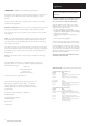
15.0 Domestic Hot Water LED Light - Green Flame Failure LED Light - Red Low High Reset Burner ON LED Light - Green Fault Finding Before performing fault finding carry out preliminary electrical checks for earth, continuity and polarity. See Section 8.13 ON Mains ON LED Light - Green LED Lights ON Low Off Off Off Off YES High Go to Electrical Supply section of the fault finding instructions.
LED Lights ELECTRICAL SUPPLY ON Off Off Off Off 15.0 Fault Finding A NO Connect Mains to boiler. 240V at A ? YES NO 240V at B ? Check wiring from terminal block to PCB. YES NO PCB fuse OK ? Check for shorts on pump, fan & gas valve. Replace if shorted & replace fuse. YES Replace PCB.
LED Lights DRY-FIRE ON Is the system full of water ? NO 15.0 Off On Flash Flash Fault Finding Pump Plug (when unplugged) Fill system with water and bleed out all air. E Viewed from Wire Entry end C YES With water flowing out of a fully open DHW tap does the pump run ? NO Unplug the pump is there 240V at C ? Unplug 5-way PCB connector. With water flowing out of a fully open DHW tap is there continuity at E? Is there 240V at D ? YES YES YES NO Pump fault.
LED Lights Ignition Lockout ON Is there gas at gas valve inlet ? NO 15.0 Off On Off On Fault Finding F Check isolation valve and gas supply. G YES Reset lockout. Is there gas flow ? (check at the meter) Remove 5-way connector from gas valve. Is there 240Vdc between F & G during ignition ? NO YES YES Replace gas valve. NO Is there at least 18mbar dynamic at gas valve inlet ? NO Remove the larger of the two 6-way PCB connectors.
LED Lights OVERHEAT LOCKOUT ON Disconnect black stat on flow pipe. When flow < 60° C is there continuity across stat ? Off Flash Off On 15.0 Fault Finding NO Replace Stat. YES Reconnect stat. Disconnect fan stat. When fan temp < 60° C is there continuity across stat ? NO Replace Stat. YES Reconnect stat. Disconnect the larger of the 6-way PCB connectors. Is there continuity across M ? NO Wiring from PCB to thermostats faulty. YES Disconnect thermistor (red sensor on flow pipe).
FAN LED Lights ON Unplug 3-way PCB connector & unplug fan. Is there continuity from K to L & from M to N ? 15.0 Off Flash Flash On Fault Finding NOTE: The fan is supplied with 325 Vdc. Fan Fault Finding should only be carried out after the boiler has been electrically isolated. NO Rectify wiring. Fan Connection PCB Connection YES L K Unplug the smaller of the 6-way PCB connectors. Is there continuity from O to P & from Q to T & from S to R ? N NO M Rectify wiring.
Off On Flash On LED Lights FLOW THERMISTOR ON Unplug flow thermistor, Is thermistor resistance between 0.5kΩ & 20kΩ ? 15.0 Fault Finding NO V Replace flow thermistor. YES Plug in thermistor, unplug 8-way PCB connector. Is resistance at V between 0.5kΩ & 20kΩ ? Viewed from Wire Entry end NO Wiring from PCB to flow thermistor faulty. YES Replace PCB. RETURN THERMISTOR LED Lights ON Unplug return thermistor, Is thermistor resistance between 0.
15.0 Fault Finding X DHW Fault Replace DHW Flow Switch. Viewed from Wire Entry end NO With water flowing out of a fully open DHW tap, does the DHW LED light ? NO Unplug 5-way connector from PCB. With water flowing out of a fully open DHW tap, is there continuity across X ? NO YES YES Unplug diverter valve. With DHW LED on, is there 240V from Y to Z ? Unplug 7-way PCB connector. With DHW LED on, is there 240V from B to C ? YES Is DHW flow switch blocked ? YES NO Unblock DHW Flow Switch.
15.0 Fault Finding CH Fault NO Is there 240V at D ? Wiring in 8-way terminal block from L to Prog 1 faulty. YES Link Plug NO Is there 240V at E ? Check integral timer and wiring. Check Link Plug if no timer fitted. D YES NO Is there 240V at F ? Check external controls wiring. YES NO Is there 240V at G ? Check room stat & room stat wiring OK. YES NO Is there 240V at H ? Wiring from R/S 2 to PCB faulty. YES Unplug Diverter Valve. Ensure all DHW taps are off so that DHW LED is off.
Standby. 16.0 16.1 Tap or shower switched on ? Operational Flow Chart Domestic Hot Water Mode 1. Standby: The diverter valve, pump, fan, spark generator and gas valve are off. If a tap or shower is switched on then Fan Pre-Purge occurs. YES 2. Fan Pre-Purge: The pump and fan are on while the diverter valve, spark generator and gas valve are off. After 5 seconds if the DHW temperature is less than the set point then Ignition occurs. 5 second Fan Pre-Purge. YES 3.
Standby. 16.0 Operational Flow Chart YES 16.2 Timer & Room Stat on ? 1. Standby: The diverter valve, pump, fan, spark generator and gas valve are off. If the timer and room stat are on then Diverter Valve moving to CH position occurs. 6 second Diverter Valve moving to CH position NO Timer off or room stat off ? NO Flow temperature less than set point ? 10 second Pump On. 4. Fan Pre-Purge: The diverter valve, pump and fan are on while the spark generator and gas valve are off.
17.
BENCHMARK No. 5 1 0 9 9 2 9 GAS BOILER COMMISSIONING CHECKLIST COLLECTIVE MARK BOILER SERIAL No. NOTIFICATION No.
SERVICE INTERVAL RECORD It is recommended that your heating system is serviced regularly and that you complete the appropriate Service Interval Record Below. Service Provider. Before completing the appropriate Service Interval Record below, please ensure you have carried out the service as described in the boiler manufacturer’s instructions. Always use the manufacturer’s specified spare part when replacing all controls SERVICE 1 DATE SERVICE 2 DATE ENGINEER NAME COMPANY NAME TEL No.
All descriptions and illustrations provided in this leaflet have been carefully prepared but we reserve the right to make changes and improvements in our products which may affect the accuracy of the information contained in this leaflet. All goods are sold subject to our standard Conditions of Sale which are available on request. BAXI A Trading Division of Baxi Heating UK, a division of Baxi Group Brooks House, Coventry Road, Warwick.