Installation & Servicing Instructions Baxi Combi Instant 80 HE Baxi Combi Instant 105 HE Gas Fired Wall Mounted Condensing Combination Boiler Please leave these instructions with the user
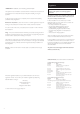
Natural Gas Baxi Combi Instant 80 HE G.C.No 47 075 17 Contents Section Baxi Combi Instant 105 HE G.C.No 47 075 19 Legislation 4 1.0 Introduction 5 2.0 General Layout 6 3.0 Appliance Operation 7 4.0 Technical Data 9 5.0 Dimensions and Fixings 11 6.0 System Details 12 Building Regulations (England & Wales) require notification of the installation of a heating appliance to the relevant Local Authority Building Control Department.
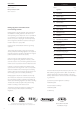
Installer Notification Guidelines Install and Commission this appliance to manufacturer's instructions Complete the Benchmark Checklist Choose Building Regulations Notification Route Competent Person's Self Certification Scheme If you notify via CORGI Scheme, CORGI will then notify the relevant Local Authority Building Control Scheme on member's behalf Building Control Contact your relevant Local Authority Building Control (LABC) who will arrange an inspection or contact a government approved inspect
Legislation IMPORTANT - Installation, Commissioning, Service & Repair This appliance must be installed in accordance with the manufacturer’s instructions and the regulations in force. Read the instructions fully before installing or using the appliance. In GB, this must be carried out by a competent person as stated in the Gas Safety (Installation & Use) Regulations.
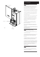
1.0 Introduction 1.1 Case Front Panel Description 1. The Baxi Combi Instant 80 HE or 105 HE is a fully automatic gas fired wall mounted condensing combination boiler. It is room sealed and fan assisted, and will serve central heating and mains fed domestic hot water. 2.The unit incorporates a small storage cylinder built into the boiler providing hot water the moment the tap is turned on. 3. The boiler is set to give a maximum output (condensing) of 25.2 kW (Instant 80 HE) or 31.0 kW (Instant 105 HE). 4.
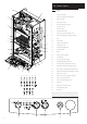
2.0 General Layout 1 2.1 Layout 20 1. Air Pressure Switch 2. Expansion Vessel & Pre-Heat Store 3. Burner Manifold 4. Automatic Air Vent 5. DHW Plate Heat Exchanger 6. Circulation Pump 7. Drain Off Point 8. Pressure Relief Valve 9. Position for Optional Integral Timer 10. Central Heating System Pressure Gauge 16 11. PCB 15 12. Control Box 13. 3-Way Valve Assembly 14. Condensate Trap 15. Flame Sensing Electrode 16. Spark Electrode 17. Burner 18.
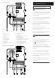
Central Heating Mode 1 3.0 Appliance Operation 28 NOTE: All delay timers mentioned in 3.1 and 3.3 are overridden by domestic hot water demand. 26 2 3 4 7 5 3.1 6 25 24 20 21 Central Heating Mode (Fig. 2) 22 17 19 1. With a demand for heating, the pump circulates water through the primary circuit. At a pre-determined flow rate the central heating flow switch operates, initiating the ignition sequence. 18 23 2.
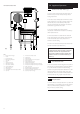
3.0 Appliance Operation Domestic Hot Water Mode 1 3.3 Domestic Hot Water Mode (Fig. 4) 28 1. Priority is given to the domestic hot water supply. A demand at a tap or shower will override any central heating requirement. 26 2 3 4 7 5 6 25 24 21 20 22 17 2. The flow of water will operate the DHW flow switch which requests the 3 way valve to change position.
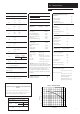
4.0 Technical Data 4.1 Appliance Type C12 Appliance Category C32 Power Consumption 170W Electrical Protection IPX5D CAT II 2H 3P Central Heating Primary Circuit Pressures kW Min NOx Class 3 24.8 10.6 Condensate Drain 1” BSP Heat Output CH (Non-Condensing) Max Min kW 24 25.2 10.1 Heat Input DHW Max kW 24.8 Heat Output DHW Max kW Max Gas Rate m3/h 24 (Natural Gas - G20) (After 10 mins) 2.
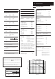
4.0 Technical Data 4.2 Appliance Type C12 Appliance Category C32 CAT II 2H 3P Heat Input CH kW Max Min 30.5 11.9 Heat Output CH (Non-Condensing) Max Min kW 29.6 31 11.
5.0 Dimensions and Fixings 3o E G Dimensions A 780mm B 345mm C 450mm A D 116mm Ø Min.
6.0 System Details 6.1 Information 1. The Baxi Combi Instant 80 HE and 105 HE Condensing Combination Boilers are ‘Water Byelaws Scheme - Approved Products’. To comply with the Water Byelaws your attention is drawn to the following installation requirements and notes (IRN). a) IRN 001 See text of entry for installation requirements and notes. b) IRN 116 Byelaw 90 and 91. c) IRN 302 Byelaw 14. 2.
6.0 System Details 6.5 System Filling and Pressurising 1. A filling point connection on the central heating return pipework must be provided to facilitate initial filling and pressurising and also any subsequent water loss replacement/refilling. Stop Valve Fig. 5 Double Check Valve DHW Mains Inlet Temporary Hose Stop Valve 2. There are connection points on the mains cold water inlet and central heating return isolating taps (Fig. 6) to which the optional filling loop kit (Part No.
6.0 System Details Other Tap Outlets 6.8 Expansion Vessel Boiler Stop Tap Fig. 8 1. All DHW circuits, connections, fittings, etc. should be fully in accordance with relevant standards, the water supply regulations. 2. Your attention is drawn to: for GB: Guidance G17 to G24 and recommendation R17 to R24 of the Water Regulations Guide. for IE: the current edition of I.S. 813 “Domestic Gas Installations”. Check Valve Pressure Reducer Valve Domestic Hot Water Circuit (Fig. 8) To Hot Taps 3.
20mm/5mm Min 450mm 5mm Min 7.0 Site Requirements see *NOTE: 7.1 200mm Min 780mm Location 1. The boiler may be fitted to any suitable wall with the flue passing through an outside wall or roof and discharging to atmosphere in a position permitting satisfactory removal of combustion products and providing an adequate air supply. The boiler should be fitted within the building unless otherwise protected by a suitable enclosure i.e. garage or outhouse.
7.0 Site Requirements 7.3 Ventilation of Compartments 1. Where the appliance is installed in a cupboard or compartment, no air vents are required as the appliance will run sufficiently cool without ventilation. 7.4 Gas Supply 1. The gas installation should be in accordance with the relevant standards. In GB this is BS 6891. In IE this is the current edition of I.S. 813 “Domestic Gas Installations”. 2.
Termination to an internal soil and vent pipe 7.0 Site Requirement 7.6 Boiler Condensate Drain FAILURE TO INSTALL THE CONDENSATE DISCHARGE PIPEWORK CORRECTLY WILL AFFECT THE RELIABLE OPERATION OF THE BOILER 50mm 2.5° M inimum per me The condensate discharge pipe MUST NOT RISE at any point along its length. There MUST be a fall of AT LEAST 2.5° (50mm per metre) along the entire run. tre of p ipe run fall 1. The condensate outlet terminates in a 1” BSP nut and seal for the connection of 21.
7.0 Site Requirements 7.7 Flue NOTE: Due to the nature of the boiler a plume of water vapour will be discharged from the flue. This should be taken into account when siting the flue terminal. 1. The following guidelines indicate the general requirements for siting flue terminals. For GB recommendations are given in BS 5440 Pt.1. For IE recommendations are given in the current edition of I.S. 813 “Domestic Gas Installations”. 2.
7.0 Site Requirements 7.8 mm 5 68 The standard horizontal flue kit allows for flue lengths between 100mm and 685mm from elbow to terminal (Fig. 14). mm 0 10 Flue Dimensions The maximum permissible equivalent flue length is: Instant 80 HE 4 metres Instant 105 HE 3 metres NOTE: Each additional 45° of flue bend will account for an equivalent flue length of 0.5m. eg. 45° = 0.5m, 90° = 2 x 45° = 1m etc. Fig. 14 7.9 Flue Trim 1.
7.0 Site Requirements 7.11 Flue Options 1. The Baxi Combi Instant 80 HE and 105 HE can be fitted with flue systems as illustrated. 2. The standard flue is suitable only for horizontal applications. 3. Maximum permissible equivalent flue lengths are:Instant Instant 80 HE 105 HE Concentric 4m 3m Vertical 4m 3m Vertical Two-Pipe 12m 12m Horizontal Flues 4. Any additional “in line” bends in the flue system must be taken into consideration.
8.0 Installation 8.1 Initial Preparation The gas supply, gas type and pressure must be checked for suitability before connection (see Section 7.4). 1. After considering the site requirements (see Section 7.0) position the fixing template on the wall ensuring it is level both horizontally and vertically. 2. Mark the position of the two most suitable fixing slots for the wall plate and boiler lower fixing holes. It is preferable to use the horizontal fixing slots. 190mm 3.
Wall Plate 8.0 Installation 8.4 Fitting The Boiler 1. Remove the sealing caps from the boiler connections. 2. Lift the boiler using the lower edges. Engage the slots at the top rear of the boiler on the wall plate (Fig. 18). 3. Insert the sealing washers between the valves and pipes on the wall plate and the boiler connections. The rubber washers must be used on the gas connection. 4. Tighten all the connections. 8.5 Fitting the Pressure Relief Discharge Pipe (Fig. 19) 1.
8.0 Installation 8.7 Fitting The Flue HORIZONTAL FLUE m 1. The standard flue is suitable for lengths between 100mm minimum and 685mm maximum, as measured from the edge of the flue elbow outlet to the joint between the terminal and air duct (Fig. 20). 5m 68 m 0m 10 2. Locate the flue elbow on the adaptor at the top of the boiler. Set the elbow to the required orientation (Fig. 21). NOTE: The flue elbow is angled at 93 degrees to ensure a fall back to the boiler. Fig. 20 3.
8.0 Installation 8.7 Waste Fitting the Flue (Cont) 5. Mark dimension ‘Y’ on the flue as shown (Fig. 23). Carefully cut the waste material from the flue, ensuring that the ducts are square and free from burrs. Y 6. The inner flue duct support bracket may be in the waste portion of the flue. In this case retrieve the bracket before discarding the waste. Flue 7. Take the inner flue support bracket (if not already fitted) and engage it over the flue duct.
8.0 Installation 8.8 Making The Electrical Connections To connect the mains input cable proceed as follows:1. Slacken the facia panel securing screws and lift the outercase panel so that its securing tabs are clear of the facia. Remove the panel. 2. Completely undo the screws securing the facia panel and hinge it down (Fig. 26). Control Box Cover Fig. 27 3. Remove the control box cover securing screws. Disengage the barbs on the control box from the cover. Remove the cover (Fig. 27). 4.
9.0 9.1 Screw Commissioning the Boiler Commissioning the Boiler 1. Reference should be made to BS 5449 Section 5 when commissioning the boiler. 2. Open the mains water supply to the boiler. Automatic Air Vent 3. Open all hot water taps to purge the DHW system. 4. Ensure that the filling loop is connected and open, then open the heating flow and return valves on the boiler. 5. Open the screw on the automatic air vent (Fig. 31). 6. The system must be flushed in accordance with BS 7593 (see Section 6.
9.0 Commissioning the Boiler OUT Burner Pressure Test Point Sealing Screw 9.2 Inlet Pressure Test Point Sealing Screw Checking the Burner Pressure 1. Turn on the gas and electrical supplies to the boiler and ensure that all external controls are calling for heat. MIN Gas Valve 2. Set the hot water and central heating temperature controls to maximum and the selector switch to the OFF position (Fig. 37). 3. Slacken the pressure test point sealing screw (Fig.
10.0 Case Front Panel 10.1 Completion Completion 1. Hinge the facia panel upwards and refit the case front panel. Tighten the securing screws (Fig. 38). 2. Instruct the user in the operation of the boiler and system, explaining the operational sequence. 3. Carefully read and complete all sections of the Benchmark Commissioning Checklist at the rear of this publication that are relevant to the appliance and installation. These details will be required in the event of any warranty work.
11.0 Servicing the Boiler Case Front Panel 11 .1 Annual Servicing 1. For reasons of safety and economy, it is recommended that the boiler is serviced annually. Servicing must be performed by a competent person. 2. After servicing, complete the relevant Service Interval Record section of the Benchmark Commissioning Checklist at the rear of this publication. 3. Ensure that the boiler is cool. 4. Ensure that both the gas and electrical supplies to the boiler are isolated. 5.
Baffle Tab Spring Clip 11.0 11.1 Servicing the Boiler Annual Servicing (Cont) 11. Ease the front edge of the left hand baffle upwards, disengaging the spring clip. Disengage the tab on the baffle from the slot in the fan hood (Fig. 42). 12. Undo the screws securing the fan and hood to the appliance back panel. Draw the assembly forwards (Fig. 43). Fig. 42 13. Undo the screws securing the burner to the injector manifold.
12.0 IMPORTANT: When changing components ensure that both the gas and electrical supplies to the boiler are isolated before any work is started. When the new component has been fitted turn the selector switch fully anticlockwise against the spring pressure to position R and hold for 2 seconds to reset the boiler before recommissioning. Pressure Switch Sensing Tubes L -’ve See Section 11.1 “Annual Servicing” for removal of case panel, door etc. H +’ve bk 12.1 Fig.
12.0 12.3 Changing Components Heat Exchanger (Fig. 50) 1. Remove the fan as described in section 12.1. 2. Drain the primary circuit. Prise the three pipe connecting clips off the joints in the flow and return pipes. Remove the heat exchanger return pipe. 3. Lift the heat exchanger to disconnect the flow pipe joint. Withdraw it from the appliance, taking care not to damage the rear insulation piece. Pipe Connecting Clips Heat Exchanger Return Pipe 4. Fit the new heat exchanger. 5.
12.0 Injector Manifold Inlet Elbow 12.5 Changing Components Injectors (Fig. 52) 1. Remove the burner as described in Section 12.4. Gasket 2. Undo the screws securing the injector manifold to the inlet elbow and remove the manifold. 3. Unscrew and replace injectors as required and examine the sealing gasket, replacing as necessary. Reassemble in reverse order. Injector 12.6 Electrodes (Fig. 52) Burner Electrodes Fig. 52 Electrode Grommets 1.
12.0 12.8 Changing Components Gas Valve (Fig. 54) 1. Undo the nut on the gas feed pipe under the boiler. Modulator Wires 2. completely undo the securing screws and hinge the facia panel down. Ignition Lead Gas Valve 3. Disconnect the wires from the valve modulator and the ignition lead from the spark generator. Disconnect the pressure sensing pipe from the valve. Undo the screw securing the spark generator electrical plug to the valve and disconnect the plug. 4.
12.0 12.12 Changing Components Pump - Head Only (Fig. 57) 1. Drain the primary circuit and remove the socket head screws securing the pump head to the body and draw the head away. 2. Undo the screw on the pump wiring cover and remove the cover. Using a suitable flat bladed screw driver press the cable securing levers downwards to release each wire after noting their position. 3. A standard Grundfos 15-60 replacement head can now be fitted. Connect the wiring to the new head.
12.0 12.15 Changing Components Pressure Gauge (Figs. 60 & 61) 1. Drain the primary circuit and undo the nut on the pressure gauge capillary. 2. Remove the timer cover and ease the timer wiring aside. Undo the screws securing the gauge retaining bracket. Fig. 60 Pressure Gauge Capillary 3. Remove the bracket and gauge assembly. Depress the barbs on the side of the gauge and remove the retaining bracket. Gauge Retaining Bracket 4. Reassemble in reverse order. 12.
12.0 12.18 Changing Components Pressure Relief Valve (Fig. 64) 1. Drain the primary circuit. 2. Disconnect the discharge pipe from the valve. Using a suitable hexagon key undo the grub screw sufficiently to release the valve. 3. Note the orientation of the valve, rotate it and withdraw it from the manifold. 4. Fit the new valve and ‘O’ ring seal and set to the previously noted orientation. Reassemble in reverse order. ‘O’ ring seal 12.19 P.C.B. (Fig. 66) 1.
12.0 Changing Components Plate Heat Exchanger 12.21 Plate Heat Exchanger (Fig. 67) 1. Drain the primary circuit. 2. While supporting the heat exchanger undo the screws securing it to the brass manifolds. 3. Withdraw the heat exchanger upwards and to the left of the gas valve, taking care not to damage any wires or controls. Rubber Seal Seals 4. There are four rubber seals between the manifolds and heat exchanger which may require replacement. Offset Stud Rubber Seal Fig. 67 5.
12.0 Diverter Valve Operating Head 12.22 Changing Components Diverter Valve Assembly (Cont) CH Pressure Differential Valve Diaphragm (Fig. 70) Spring Clip 3-pin Plug 1. Isolate the boiler from the central heating flow and return pipes and drain the boiler primary circuit. Diverter Valve 2. Prise off the spring clip retaining the microswitch. Pull the switch away. Diaphragm 3. Undo the screws securing the differential valve cover. Diaphragm Spring 4.
12.0 Secondary Heat Exchanger 12.24 Changing Components Secondary Heat Exchanger (Fig. 73) 1. Drain the primary circuit Pipe Connecting Clip 2. Undo the four screws securing the right hand case panel. Remove the panel. Fan Spigot Outlet Pipe Clamp Outer Drum Boiler Return Pipe Heat Exchanger Return Pipe Elbow Fan Spigot Outlet Pipe Fig. 73 3. Prise the connecting clips from the heat exchanger return pipe and the boiler return pipe. Remove the pipes. 4.
13.
14.0 Fault Finding Carry out initial fault finding checks 1. Check that gas, water and electrical supplies are available at the boiler. Electrical supply = 230V ~ 50 Hz. CH water system pressurised to 0.5 bar when the boiler is cold. The preferred minimum gas pressure is 19.5mbar (natural gas), or 36mbar (propane). 2. Carry out electrical system checks, i.e. Ground Continuity, Resistance to Ground, Short Circuit and Polarity with a suitable meter.
14.0 Domestic Hot Water - Follow operational sequence Turn On/Off/Reset selector to position. neon illuminated. Fault Finding NO Go to section ‘A’. YES Primary water diverted to DHW preheating circuit. NO Go to section ‘M’. YES Go to section ‘L’. YES Turn preheat control to on. Preheating function starts after 25 seconds. neon flashing. NO External controls and where fitted, integral timer calling for heat. NO Ensure controls are set to demand and verify the contacts are closed.
14.0 Fault Finding Central Heating - Follow operational sequence Turn selector to neon illuminated. NO Go to section ‘A’. NO YES Turn Central Heating thermostat to maximum. neon illuminated. NO External controls calling for heat and where fitted, internal clock calling for heat. YES Ensure controls are set to demand and verify the contacts are closed. neon flashing Go to section ‘B’. YES Primary water is diverted from preheating circuit to CH system. neon illuminated. NO Go to section ‘M’.
14.0 Fault Finding Central Heating - Follow operational sequence (Continued) Continued from previous page Does the burner remain lit ? NO CH temperature higher than set point of CH thermostat control. When CH temperature decreases cycle continues. YES NO Fan runs at max speed. Go to section ‘J’ & ‘O’. neon flashing. YES NO NO Air pressure switch proved. neon flashing Go to section ‘E’. neons flashing Go to section ‘D’. Turn selector to the reset position.
14.0 Fault Finding Fault Finding Solutions A Is there 230V at: 1. 2. 3. B NO Main terminals L and N Check electrical supply YES Main terminal fuse Selector terminals a & b and a & 3. PCB - A4 connector terminals 4 & 5 Replace fuse NO Check wiring Replace selector neon illuminated NO Is there 230V at: YES 1. Pump 2. PCB - A4 connector terminals NO If pump jammed, release NO Replace pump Replace main PCB YES Change pump supply cable C 1. 2. 3. NO CH system pressure 0.5 to 1.
14.0 Fault Finding Fault Finding Solutions E F Check and correct if necessary 1. Electrical and pressure tube connections 2. Blockage of pressure tubes 3. Restriction in flue 4. Venturi Gas at burner NO NO Replace air pressure switch Ensure gas is on and purged YES PCB - A1 connector has 230V across terminals 2 & 4 Replace gas valve NO neon flashing YES Turn selector switch to reset position R NO Replace main PCB G 1.
14.0 Fault Finding Fault Finding Solutions I Ensure that mains input terminal L is Live (230V) and N is Neutral (0V) YES Check and correct if necessary 1. Flame sensing electrode and lead connections 2. Flame sensing electrode position YES Flame current should be 1 µA approx. J Overheat thermostat operated or faulty, i.e. continuity across thermostat terminals Replace main PCB NO Replace flame sensing electrode Allow to cool. Continuity across thermostat terminals more than 1.
15.0 Short Parts List Short Parts List 44 140 22 Key No. G.C. No. 22 Description Manufacturers Part No.
BENCHMARK No. 5 1 1 1 8 0 7 GAS BOILER COMMISSIONING CHECKLIST COLLECTIVE MARK BOILER SERIAL No. NOTIFICATION No.
SERVICE INTERVAL RECORD It is recommended that your heating system is serviced regularly and that you complete the appropriate Service Interval Record Below. Service Provider. Before completing the appropriate Service Interval Record below, please ensure you have carried out the service as described in the boiler manufacturer’s instructions. Always use the manufacturer’s specified spare part when replacing all controls SERVICE 1 DATE SERVICE 2 DATE ENGINEER NAME COMPANY NAME TEL No.
B A X I P OTTERTO N 923.612.2 A Trading Division of Baxi Heating UK Ltd Brownedge Road Bamber Bridge Preston Lancashire PR5 6UP After Sales Service 08706 096 096 Technical Enquiries 08706 049 049 Website www.baxi.co.