
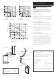
Technical data

30
10.0 Installation
© Baxi Heating UK Ltd 2007
10.6 Fitting The Flue
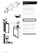
HORIZONTAL TELESCOPIC FLUE
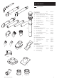
1. There are two telescopic sections, the Terminal
Assembly and the Connection Assembly, a roll of sealing
tape and two self tapping screws. A 93° elbow is also
supplied. The outer duct of the Connection Assembly is
painted white. On the Terminal Assembly the outer duct is
unpainted.
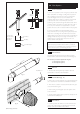
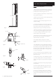
2. The two sections can be adjusted to provide a length
between 315mm and 500mm (Fig. 39) when measured
from the flue elbow (there is 50mm engagement into the
elbow).
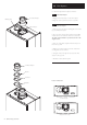
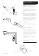
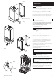
3. Locate the flue elbow on the adaptor at the top of the
boiler. Set the elbow to the required orientation (Fig. 41).
NOTE: The flue elbow is angled at 93 degrees to
ensure a fall back to the boiler.
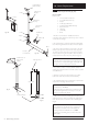
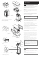
4. Measure the distance from the outside wall face to the
elbow. This dimension will be known as ‘X’ (Fig. 40).
5. If the distance from the flue elbow to the outside face of
the wall (‘X’ in Fig. 40) is less than 250mm the Connection
Assembly can be discarded and the Terminal Assembly
fitted directly into the elbow.
6. In instances where the dimension ‘X’ (Fig. 40) is between
250mm and 315mm it will be necessary to shorten the
Terminal Assembly by careful cutting to accommodate
walls of these thicknesses.
7. To dimension ‘X’ add 50mm. This dimension to be
known as ‘Y’.
Wall Thickness
(X)
Wall Thickness
(X)
Flue Elbow
Fig. 39
Fig. 41
Adaptor
Apply Lubricant for
ease of assembly.
Ensure Elbow is fully
engaged into Boiler
Adaptor
315mm 500mm
20mm
Indicator line
Terminal Assembly
Connection Assembly
Fig. 40