
Quick Start Manual


7212140 - 02 (06/14) EcoBlue System 57
Maintenance
10
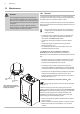
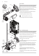
10.3.6 Flue Sensor
1. For ease of access remove the Expansion Vessel on 12 - 15 -
18 - 24 - 28 models as described in Section 10.3.18.
2. Ease the retaining tab on the sensor away and disconnect the
electrical plug.
3. Turn the sensor 90° anticlockwise to remove - it is a bayonet
connection.
4. Reassemble in reverse order.
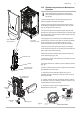
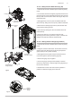
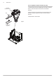
10.3.7 Igniter (Fig. 54)
1. Note the position of the ignition & sensing leads and
disconnect them. Also disconnect the igniter feed plug.
2. Undo the screw securing the igniter mounting bracket to the
left hand side panel. Remove the igniter and bracket and
transfer the bracket to the new igniter.
3. Reassemble in reverse order, reconnecting the plug and
leads to the igniter.
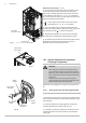
10.3.8 Heating Flow & Return Sensors (Fig. 55)
1. There is one sensor on the flow (red wires) and one sensor
on the return (blue wires). Note: For access to the return sensor
first remove the fan and air/gas collector (see 10.3.2).
2. After noting the position prise the sensor clip off the pipe and
disconnect the plug.
3. Connect the plug to the new sensor and ease the clip onto
the pipe as close to the heat exchanger as possible.
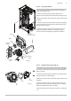
10.3.9 Safety Thermostat (Fig. 55)
1. Pull the two spade connections off the safety thermostat.
2. Remove the screws securing the thermostat to the mounting
plate on the flow pipe.
3. Reassemble in reverse order, ensuring that the connections
are pushed fully on.
Flue Sensor
Electrical
Plug
Fig. 54
Heating Flow
Sensor
Fig. 55
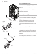
DHW NTC Sensor
Fig. 56
Control Box
removed for clarity
Safety
Thermostat
Igniter
Mounting
Bracket
Spark
Connection (‘A’)
Earth
Connection (‘B’)