Installation & Servicing Instructions Ecogen 24/1.0 Gas Fired Wall Mounted Condensing Boiler and Power Generator These instructions include the Benchmark Commissioning Checklist and should be left with the user for safe keeping.
Natural Gas Propane Baxi Ecogen 24/1.0 G.C.No 41 075 60 Baxi Ecogen 24/1.0 LPG G.C.No 41 075 64 This appliance contains a pressure vessel filled with Helium to 23 bar. Do not strike, drop, drill or puncture the vessel. Do not unbolt any of the covers or flanges. The vessel contains no user serviceable parts. Dispose of safely - see section 18.0 for further safety information.
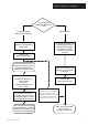
Installer Notification Guidelines Choose Building Regulations Notification Route Competent Person's Self Certification Scheme Building Control Install and Commission this appliance to manufacturer's instructions Contact your relevant Local Authority Building Control (LABC) who will arrange an inspection or contact a government approved inspector Complete the Benchmark Checklist If you notify via the ‘Gas Safe Register’, the register will issue the Building Regulations certificate on members’ behalf
Legislation IMPORTANT - Installation, Commissioning, Service & Repair This appliance must be installed in accordance with the manufacturer’s instructions and the regulations in force. Read the instructions fully before installing or using the appliance. In GB, this must be carried out by a competent person as stated in the Gas Safety (Installation & Use) Regulations and Part P of the Electrical Regulations.
Safe Manual Handling General The following advice should be adhered to, from when first handling the boiler to the final stages of installation, and also during maintenance. Most injuries as a result of inappropriate handling and lifting are to the back, but all other parts of the body are vulnerable, particularly shoulders, arms and hands. Health & Safety is the responsibility of EVERYONE. There is no ‘safe’ limit for one man - each person has different capabilities.
CONTENTS Section 6 © Baxi Heating UK Ltd 2012 Page 1.0 Introduction 7 2.0 General Layout 8 3.0 Appliance Operation 9 4.0 Technical Data 10 5.0 Dimensions and Fixings 11 6.0 System Details 12 7.0 Site Requirements 16 8.0 Flue Options 24 9.0 Installation 33 10.0 Electrical 37 11.0 Commissioning 51 12.0 Completion 57 13.0 Servicing 58 14.0 Changing Components 61 15.0 Combustion Check 68 16.0 Schematic Wiring 70 17.0 Fault Finding 76 18.
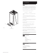
1.0 Introduction 1.1 Description 1. The Baxi Ecogen 24/1.0 is a fully automatic gas fired wall mounted condensing heat only boiler which will produce up to 1kW of electricity for use by the householder. Any electricity excess to requirements at the time of production will be fed back into the national grid. It is room sealed and fan assisted. 2. The boiler is set to give a maximum output of :24 kW (Heat), 1kW (Electric) 3. The boiler is suitable for use only on fully pumped sealed systems. 4.
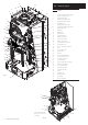
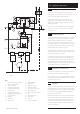
12 25 36 2.0 General Layout 26 17 2.1 11 16 15 1 3 21 2 34 22 4 23 19 6 20 33 34 7 5 8 27 9 28 35 10 13 18 14 Fig.
3.0 Appliance Operation 3.1 1. With a demand for heating or hot water, the pump circulates water through the primary circuit. If the flow is 4.0 L/min or above the ignition sequence will start. 1 3 2. When the flow temperature reaches the set point temperature, a 5 minute delay occurs before the burner relights automatically (anti-cycling). The pump continues to run during this period. 4 2 16 15 17 11 Operating Mode (Fig. 3) 18 8 6 3.2 7 14 3.
4.0 Technical Data 4.1 Country - GB/IE - Natural Gas Appliance Category CAT I 2H Max Gas Rate (m3/hr) Both 2.68 Engine 0.82 Injector (mm) Engine 4.1 Appliance Type Supplementary 1.86 Supplementary 5.6 C13 C33 C53 NOx Class Safety Discharge Max Operating Min Operating Recommended Operating Range 150W Electrical Protection Country - GB/IE - Propane Gas Appliance Category Max Gas Rate (m3/hr) Both 1.04 Engine 0.32 Injector (mm) Engine 3.0 Supplementary 0.72 Supplementary 4.
5.0 Dimensions and Fixings Dimensions At Least 1.5° A 950mm E G B 426mm C 450mm D 116mm Ø Min.
6.0 System Details 6.1 Water Circulating Systems 1. The appliance is only suitable for use on sealed systems. 2. Ideally fit a new sealed heating system to Building Regulations part L1 (2010). If an existing sealed system is to be used the following procedure must be completed before the Ecogen is installed. • The system must be cleaned with Fernox F3 • Power flush the system according to the power flush equipment supplier’s instructions.
6.0 System Details 6.3 Pipework 1. The sizes of flow and return pipes from the boiler should be determined by normal methods, according to the requirements of the system. The connections to the boiler will accept 22mm pipe fittings. Compression fittings must be used to prevent heat damage to the boiler (as supplied see Section 9.3). Copper 0.5m Copper 0.5m Flow Boiler Return Copper 1m Fig. 4 2.
6.0 System Details Manual Air Vent Safety Valve Filling Loop Pressure Gauge Pump Magnetic Cleaner Boiler 6.6 Expansion Vessel Radiator Circuit System Drains at Low Point Fig. 8 Method of determining minimum valve of expansion vessel volume for sealed systems Vessel Charge Pressure (Bar) Initial System Pressure (Bar) Multiply Total Water Content Of System By (Litres) 1.0 1.0 1.5 2.0 0.087 0.152 0.330 1.5 2.0 0.125 0.265 1.5 Table.
6.0 System Details 6.7 All wired connections Operator Unit Room Unit 1 Kit A or D 1. A THINK Controller is mounted on the appliance as standard (It can be mounted on a wall cradle and configured to use as an room sensor). Room Unit 2 Kit D IMPORTANT: Before running the appliance ensure parameter 5700 has been set according to the type of system installed. See sections 10.4 to 10.11 for system types and section 11.3.k for the change procedure. Wired Cradles 1a 2.
5mm Min 450mm 60mm Min 7.0 Site Requirements 250mm Min 7.1 Location 1. Must not be located in a living space (recommend locations, garage, utility, and outhouse). 2. There must be sufficient space at the installation location and in the route to the location for manoeuvring and operating the lifting equipment (Genie GL-8 lifting equipment dimensions are 64cm wide x 175cm high x 95cm deep). This space must be maintained for future access of the lifting equipment for maintenance. 950mm 3.
7.0 Site Requirement 7.4 Test Nipple Gas Supply 1. The gas installation should be in accordance with the relevant standards. In GB this is BS 6891 (Natural Gas) or BS 5482-1 (Propane Gas). In IE this is the current edition of I.S. 813 “Domestic Gas Installations”. Off Position View from under appliance Gas Service Cock On Position 2. A gas service cock is supplied to enable connection using 15mm copper pipe (Fig. 11). 3.
7.0 Site Requirements PSR 0.5 0.6 0.7 0.8 0.9 1 1.1 1.2 1.3 1.4 1.5 to 4 7.6 HPER 0.295 0.282 0.269 0.256 0.243 0.231 0.225 0.219 0.213 0.207 0.201 Heating Plant Emissions Rate (HPER) 1. To enable the house holder to claim the Feed in tariff (FIT) the heating plant emission rate must be calculated and entered into the MCS certification submission and recorded in the Micro chp system commissioning checklist benchmark sheets at the back of these instructions.
IMPORTANT: In designing a connection for the Ecogen 24/1.0 the electrical installer has to consider all the issues that would need to be covered for a conventional final circuit, including:In Accordance with BS: 7671.
Examples are shown of the following methods of termination:i) to an internal soil & vent pipe ii) via an internal discharge branch (e.g. sink waste) downstream of the trap iii) to a drain or gully iv) to a purpose made soakaway v) pumped into an internal discharge branch (e.g. sink waste) downstream of the trap vi) pumped into an external soil & vent pipe vii) to a drain or gully with extended external run & trace heating It is strongly recommended to discharge internally into the household drainage system.
7.0 Site Requirements 7.8 iii) Termination to a drain or gully Boiler 50mm Pipe must terminate above water level but below surrounding surface. Cut end at 45° per me tre of 2.5° M inimum Condensate Drain (cont.) 11. When discharging condensate into a soil stack or waste pipe the effects of existing plumbing must be considered.
v) pumped into an internal discharge branch (e.g. sink waste) downstream of the trap Sink 50mm 7.0 Site Requirement per me tre of p ipe run 2.5° M inimum fall Pipe must terminate above water level but below surrounding surface. Cut end at 45° 7.8 Condensate Drain (cont.) 12. A boiler discharge pump is available, ‘MULTIFIT’ part no. 720648301. This pump will dispose of both condensate & high temperature water from the relief valve. It has a maximum head of 5 metres.
Terminal Position with Minimum Distance (Fig. 15) (mm) A1 Directly below an opening, air brick, opening windows, etc. B1 Above an opening, air brick, opening window etc. C1 Horizontally to an opening, air brick, opening window etc. D2 Below gutters, soil pipes or drain pipes. E2 Below eaves. F2 Below balconies or car port roof. G2 From a vertical drain pipe or soil pipe. H2 From an internal or external corner. I Above ground, roof or balcony level. J From a surface or boundary line facing a terminal.
8.0 Flue Options 8.1 Horizontal Flue Systems 1. The standard flue is suitable only for horizontal termination applications. Y 2. All fittings should be fully engaged. The approximate engagement is 40 mm. Use the lubrication provided in the kit to aid assembly. X 3. For long flue runs allow 5 mm per metre for expansion. 4. Maximum permissible equivalent flue lengths are:Horizontal Concentric (60/100) 5 metres Horizontal Flues 5.
Vertical Flues (Twin Pipe) 8.0 Flue Options 8.2 Twin & Vertical Flue Systems 1. Maximum permissible equivalent flue lengths are:Vertical Concentric (60/100) Vertical Twin Pipe (80/80) Y 5 metres 10 metres 2. Any additional “in line” bends in the flue system must be taken into consideration. Their equivalent lengths are:Concentric Pipes: 135° bend 0.5 metres 93° bend 1.0 metres Twin Flue Pipe 135° bend 0.25 metres 91.5° bend 0.
8.0 Flue Options 8.
8.0 Flue Options For Twin Flue Systems fit the adaptors as follows:- 8.4 Flue Duct Adaptor (Fig. 17) Flue Duct Adaptor 1. Engage the flue adaptor on the boiler adaptor, making sure that it is pushed down as far as possible. Boiler Adaptor 8.5 Air duct adaptor (Fig. 18) Blanking Plate 1. Undo the screws securing the blanking plate to the boiler top panel. Discard the plate. 2. Take one of the gaskets supplied in the kit and place on the boiler top panel. 3.
8.0 Flue Options 8.6 1. In the case of a pitched roof 25 - 50 degrees, position the lead tile to replace/flash over existing roof tiling. Make an aperture in the roof suitable for the lower tube of the roof terminal and ensure the integrity of the roof cover is maintained. The adjustable plastic collar can either be positioned on the lead tile or the lower tube of the roof terminal prior to the final positioning of the vertical flue through the tile.
93° Elbow/Plume Outlet Assembly 8.0 Flue Options 8.11 60Ø Support Bracket O Ring Kit No 5118638 Content of kit 1 0.9m 60/100 Concentric Flue 1 1m 60 Dia Exhaust Flue Pipe 1 Adaptor 2 60 Dia Support Brackets 1 93° Elbow/Plume Outlet Assembly 1 Flexible Flue Trim 3 “O” Rings 1 ‘Jubilee Clip 1 Elbow 0.9 metres 60Ø Exhaust Flue Pipe 60Ø Support Bracket O Ring Fig. 21a Plume Displacement Kit (Fig. 21b) Flexible Flue Trim 1.
8.0 Flue Options 7 60 Ø Exhaust (metres) X 8 7 60 Ø Exhaust (metres) X 8 6 5 4 3 4 3 1 1 0 0 2 3 4 5 6 7 8 In the graph the solid line diagonal represents the relationship between the concentric flue assembly (and any extensions) and the 60Ø exhaust (and any extensions or additional bends).
8.0 Flue Options 8.13 General Fitting Notes NOTE: The flue system may only be installed as described in this section 1. Cut a hole in the external wall which the concentric flue assembly will pass through. The hole should allow the flue to fall back to the boiler at an angle of 1.5° to 3°. Min. 2 metres 2. When completed the terminal must be at least 2 metres above ground level (Fig. 21g). 3. Measure and cut to size the concentric assembly and any extensions that are being used. 4.
8.0 Flue Options Plume Outlet Elbow 8.13 General Fitting Notes (cont.) 15. For aesthetic purposes it is permissible to route the 60Ø exhaust in an enclosed box, but the air inlet and plume outlet MUST remain in free air. 16. It is also possible to separate the plume outlet from the 93° elbow to allow the flue to be installed as shown in Fig. 21n. 50 0m m Mi n. 17. To do this, first slacken the two screws retaining the plume outlet to the elbow, and remove the outlet (Fig. 21p).
9.0 Installation NOTE: - Installers of this appliance must have undergone Baxi Ecogen Training and been approved to install this appliance. 9.1 Unpacking & Initial Preparation NOTE: Maintain the appliance upright at all times. Do not lay the appliance on its back, sides or front. Drilling of the wall or ceiling for flue and pipe work must be completed before the appliance is fitted to the wall. Fig. 22 Fig.
Wall Plate 9.0 Installation Ensure that there is adequate clearance for the lifting equipment. 9.2 Bottom edge of Appliance to rest on Bracket 60mm Engage Securing Nuts and tighten to secure appliance 60mm Fig. 27 Fitting The Boiler 1. Using a suitable lifting device, lift the appliance on its base packaging. Offer the appliance up to the wall plate and engage the bottom edge of the back of the appliance on to the wall plate (Figs. 27 & 28).
9.0 Installation 9.5 m 0m 50 Fitting The Flue HORIZONTAL TELESCOPIC FLUE m m 15 3 Terminal Assembly 1. There are two telescopic sections, the Terminal Assembly and the Connection Assembly, a roll of sealing tape and two self tapping screws. A 93° elbow is also supplied. The outer duct of the Connection Assembly is painted white. On the Terminal Assembly the outer duct is unpainted. 2. The two sections can be adjusted to provide a length between 315mm and 500mm (Fig.
9.0 Installation ’ ‘Y ion ens Dim 9.5 Fitting the Flue (Cont) Securing Screw Fig. 34 ‘Peak’ to be uppermost 8. Adjust the two telescopic sections to dimension ‘Y’ (Fig. 34). Ensure that the rivets and holes in the Connection Assembly are aligned horizontally (Fig. 35). 9. Using a 2mm bit, drill through the holes at the end of the Connection Assembly into the Terminal Assembly and secure them together using the screws supplied (Fig. 34). Seal the joint with the tape provided (Fig. 36).
10.0 Electrical 10.1 Making The Electrical Connections This appliance shall be connected to a suitably protected electrical supply i.e., 16A - see section 7.7. NOTE: Ensure all cables are secured using the cable clamps provided. When accessing the appliance controls area, take care not to let the control box drop down in an uncontrolled manner as this may cause damage. 1.
10.0 Electrical 10.3 Complete Wiring Configuration 1. All wiring external to the appliance must be in accordance with I.E.E. BS 7671 - requirements for Electrical Installations. IMPORTANT: Before running the appliance ensure parameter 5700 has been set according to the type of system installed. See sections 10.4 to 10.11 for system types and section 11.3.k for the change procedure.
10.0 Electrical Intelligent Installations 10.4 Y-Plan with DHW cylinder sensor 1. The appliance MUST have a permanent Live/Neutral/Earth connection. The pump must be connected to the appliance as shown. 2. Set parameter 5700 to ‘2’ for one heating circuit - see section 11.3.k. NOTE: It is not possible to operate a second heating circuit with a Y-Plan system. E Mains Supply.
10.0 Electrical Intelligent Installations 10.5 Y-Plan with DHW cylinder Thermostat 1. The appliance MUST have a permanent Live/Neutral/Earth connection. The pump must be connected to the appliance as shown. 2. Set parameter 5700 to ‘2’ for one heating circuit - see section 11.3.k. 3. The DHW set point on the THINK Controller must be the same as the thermostat set point on the cylinder. If this is not done the DHW temperature may not be achieved or the recovery time will be increased.
10.0 Electrical Intelligent Installations 10.6 W-Plan with DHW cylinder sensor 1. The appliance MUST have a permanent Live/Neutral/Earth connection. The pump must be connected to the appliance as shown. 2. Set parameter 5700 to ‘2’ for one heating circuit - see section 11.3.k. 3. The rest port of the 3 port valve needs to be connected to the central heating circuit so that the valve is driven to the DHW position.
10.0 Electrical Intelligent Installations 10.7 W-Plan with DHW cylinder thermostat 1. The appliance MUST have a permanent Live/Neutral/Earth connection. The pump must be connected to the appliance as shown. 2. Set parameter 5700 to ‘2’ for one heating circuit - see section 11.3.k. 3. The rest port of the 3 port valve needs to be connected to the central heating circuit so that the valve is driven to the DHW position.
10.0 Electrical Intelligent Installations 10.8 S-Plan with DHW Cylinder sensor 1. The appliance MUST have a permanent Live/Neutral/Earth connection. The pump must be connected to the appliance as shown. 2. Set parameter 5700 to ‘2’ for one heating circuit - see section 11.3.k. E Mains Supply.
10.0 Electrical Intelligent Installations 10.9 S-Plan with DHW Cylinder Thermostat 1. The appliance MUST have a permanent Live/Neutral/Earth connection. The pump must be connected to the appliance as shown. 2. Set parameter 5700 to ‘2’ for one heating circuit - see section 11.3.k. 3. The DHW set point on the THINK Controller must be the same as the thermostat set point on the cylinder. If this is not done the DHW temperature may not be achieved or the recovery time will be increased. E Mains Supply.
10.0 Electrical Intelligent Installations 10.10 S-Plan with 2nd Heating Circuit 1. The appliance MUST have a permanent Live/Neutral/Earth connection. The pump must be connected to the appliance as shown. 2. Set parameter 5700 to ‘3’ for two heating circuits - see section 11.3.k. 3. To control the second heating circuit a second THINK Controller is required – this is available as an optional extra. For guidance on installing the second THINK Controller see section 11.3 paragraph k.
10.0 Electrical Retro Installations NOTE: This installation is used only if the user wishes to utilise their existing temperature and time controls. Outside and DHW sensors cannot be used. The THINK Controller must remain on the appliance. 10.11 Wiring Center NOTE: As the boiler does not know what the actual room or DHW temperature is, the boiler temperature is fixed at 80°C. Appliance MUST have a permanent Live/Neutral/Earth connection. Pump MUST be connected directly to the appliance.
10.0 Electrical Display showing all available segments 10.12 THINK Controller, 5 LED Receiver and Wall Cradle Accessory (Figs.
10.0 Electrical 10.13 To Configure the THINK Controller as a Room Sensor (cont) 3. Press the menu button repeatedly until the standard screen is available. The Programmable Room Unit symbol should be shown on the screen if the THINK Controller has been configured correctly, see Fig. 42. Wiring connections to appliance - see Section 16.6 Wired THINK Controller Wall Cradle Control Terminal Function 1 Power supply 12v 2 Ground (0v) 3 Data Signal (+v) 4.
10.0 Electrical 10.15 Room Unit Installation Procedure 1. Room unit location: The wall cradle should be located in the main living room while giving consideration to the following points: Min. 200 mm 1500 mm The place of installation should be chosen such that the sensor can capture the room temperature as accurately as possible without getting adversely affected by direct solar radiation or other heat or refrigeration sources (about 1.5 meters above the floor) (Fig. 45).
10.0 Electrical 10.17 Wireless Installation 1. If a wireless system is being installed then communication must be establish between the various RF components and the special RF 5 LED Receiver which contains the transceiver for the appliance. Each kit as outlined in section 6.8 includes installation instructions. An overview is given below: - NOTE: The THINK Controller refresh rate will be slower than when it is mounted directly on the appliance or in a wired cradle. 2.
11.0 Commissioning 11.1 Preliminary Electrical Checks 1. Reference should be made to BS:EN 12828, 14336 and 5449 Section 5 when commissioning the boiler. 2. Prior to commissioning the boiler preliminary electrical system checks should be carried out. 3. Remove the outercase, the bottom panel and lower the control tray to gain access to the electrical connections (see section 10.1). Top Centre Transit Bracket Fig. 48 4.
11.0 Commissioning 11.3 Commissioning of Controls Every time the appliance is powered up, the controls carries out 2 checking functions a) 315: Initialization – Main PCB gathers data on connections and sensors. This takes around 2 minutes. b) 312: Deaeration Function – all circulation valves are opened and the circulating pump is exercised. On for 6 seconds off for 5 seconds for 4.5 minutes. See section g) Deaeration function A number of actions are required to complete the commissioning procedure.
11.0 Commissioning 11.3 Commissioning of Controls (cont) d) DHW set point for thermostat control. Remember: Make sure the user DHW setpoint on the THINK Controller is equal to or greater than the set point on the thermostat at the cylinder. If this procedure is not performed the recovery time of the DHW maybe be increased unacceptably. e) Time Program Setting Please refer to the User’s Operating Instructions Section 5 (CH) and Section 6 (DHW). f) Chimney Sweep - Checking the gas rates - see Section 11.5.
11.0 Commissioning 11.3 Commissioning of Controls (cont) j) Legionella Legionella is only possible if DHW cylinder sensor is used. The function default activation time is ‘Monday at 8:00am’. • To modify the legionella time press ‘Menu’ button to enter the programming menu. • Scroll to and select ‘Domestic Hot Water’. • Scroll to and select ‘Legionella function weekday’ • Change and confirm new day. • Select ‘Legionella funct time’. • Change and confirm new time.
11.0 Commissioning 11.4 Saving the sensor connections 1. For intelligent installations where sensors are used, after all of the connections are made and all the THINK Controller’s have been programmed as room sensors, the sensor connections need to be saved. 2. From the main screen: • Press the Menu Button to reveal ‘Information’. • Press and hold Easy Menu + Menu for 5 seconds to reveal ‘user’. • Turn the Selector Button to highlight ‘commissioning’ and press to select.
11.0 Commissioning 11.5 Starting the Appliance and Checking the Gas Rate 1. The gas valve is factory set and in normal running the burner pressure cannot be measured as it is controlled by the fan and modulates as demand on the boiler alters. 2. The gas rate must be checked (as in accordance with Gas Regulation 98 Paragraph 26/9) with any other appliances and pilot lights turned off. 3. The gas rate measurement may be made with the Engine and Supplementary burners both on maximum.
11.0 Commissioning 11.5 Starting the Appliance and Checking the Gas Rate (cont) 10. Carry out the rate measurement. The burners will remain at maximum rate unless: a) A fault condition occurs – the burner/s will switch off – depending on the fault. b) The boiler set flow condition is reached (see note) – the burners will switch off. c) The power generated reaches 1kW - the engine burner will modulate down.
13.0 Servicing 13.1 1. For reasons of safety and economy, it is recommended that the appliance is serviced annually. Servicing must be performed by a competent person in accordance with BS 7967-4:2007. Throttle Adjustment Screw (cover removed) 2. After servicing, complete the relevant Service Interval Record section of the Benchmark Commissioning Checklist at the rear of this publication.
13.0 Servicing 13.3 Servicing - Internal Integrity Safety Note: Before removing the front cover; the correct shut down sequence must be followed for your own safety. Before servicing, ensure that the boiler is cool with the engine head below 120°C – otherwise there is a risk of electric shock even with the supplies disconnected. The head temperature may be accessed via the THINK Controller. Press the MENU Button. Turn the Selector Button to highlight ‘Information’. Press the Button to select.
13.0 Servicing 13.4 Servicing – Combustion and Rate Checks 1. Perform combustion and rate checks by using the chimney sweep mode to force each burner into maximum rate (see section 15.0 Combustion Checks). Combustion reading of CO2 ~ 8.7 – 9.3 and CO less than 100 ppm are acceptable for both burners. Measure the CO/CO2 ratio. This valve must be less than 0.004. Gaskets 2. Set each burner separately to a minimum and check that the burner stays lit with clean combustion. Igniter Electrode 3.