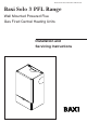
Please leave these instructions with the user Baxi Solo 3 PFL Range Wall Mounted Powered Flue Gas Fired Central Heating Units Installation and Servicing Instructions
Natural Gas Baxi Solo 3 PFL 30 G.C.No. 41 075 20 Baxi Solo 3 PFL 40 G.C.No. 41 075 21 Baxi Solo 3 PFL 50 G.C.No. 41 075 22 Baxi Solo 3 PFL 60 G.C.No. 41 075 23 Baxi Solo 3 PFL 70 G.C.No. 41 075 24 Baxi Solo 3 PFL 80 G.C.No. 41 075 30 Baxi UK Limited is one of the leading manufacturers of domestic heating products in the UK. Our first priority is to give a high quality service to our customers.
Contents Section Page 1.0 Introduction 4 2.0 Technical Data 5 3.0 System Details 7 4.0 Site Requirement 10 5.0 Installation 14 6.0 Commissioning the Appliance 32 7.0 Fitting the Outercase 34 8.0 Overheat Cut-Off Device 35 9.0 Annual Servicing 36 10.0 Changing Components 38 11.0 Fault Finding 42 12.0 Short Parts List 44 13.
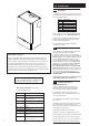
1.0 Introduction 1.1 Description 1. The Baxi Solo 3 PFL is a gas fired room sealed fan assisted central heating boiler with outputs as shown in the table below Model 30 40 50 60 70 80 Heat Output 8.79kW (30,000 Btu/h) 11.72kW (40,000 Btu/h) 14.65kW (50,000 Btu/h) 17.58kW (60,000 Btu/h) 20.5kW (70,000 Btu/h) 23.44kW (80,000 Btu/h) 2. Each appliance is preset at a heat input rating and is designed for use on NATURAL GAS only. 3.
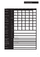
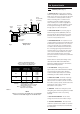
2.0 Technical Data Model 30 40 50 60 70 80 kW 8.79 11.72 14.65 17.58 20.5 23.44 Btu/h 30,000 40,000 50,000 60,000 70,000 80,000 kW 10.99 14.65 18.32 21.98 25.64 29.31 Btu/h 37,500 50,000 62,500 75,000 87,500 100,000 mbar 16.0 ±0.5 16.0 ±0.5 16.0 ±0.5 16.0 ±0.5 16.0 ±0.5 16.0 ±0.5 in wg 6.4 ±0.2 6.4 ±0.2 6.4 ±0.2 6.4 ±0.2 6.4 ±0.2 6.4 ±0.2 CV 38mj/m3 1.04m3/h 1.39m3/h 1.74m3/h 2.08m3/h 2.43m3/h 2.78m3/h 36.86ft3/h 49.0ft3/h 61.3ft3/h 73.5ft3/h 86.
2.
3.0 System Details 3.1 Option B 1. The appliance is suitable for use with open vent fully pumped systems and sealed systems where additional control protection is required. The following conditions should be observed on all systems: Option C Radiator Circuit Fig. 1 Water Circulating Systems • The static head must not exceed 30m (100ft) of water. • The boiler must not be used with a direct cylinder. • The boiler is fitted with a timed pump overrun that will operate for approximately 8 minutes.
3.0 System Details Copper 0.5m Copper 0.5m 3.3 Flow Boiler Return Pipework 1. The sizes of flow and return pipes from the boiler should be determined by normal methods, according to the requirements of the system. Copper 1m 2. An 11 °C (20°F) drop in temperature across the system is recommended. Fig. 5 mm 500 45° 1000mm Min 3. In systems using non-metallic pipework it is necessary to use copper pipe for the boiler Flow and Return.
3.0 System Details 3.6 3 Litre Top Up Bottle (if required) Air Vent Pressure Gauge Safety Valve Filling Point Sealed Systems (Fig. 9) 1. SAFETY VALVE - A safety valve complying with the requirements of BS 6283 Part 1 must be fitted close to the boiler on the flow pipe by means of a horizontal or vertically upward connection with no intervening valve or restrictions and should be positioned to facilitate testing.
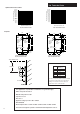
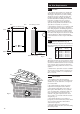
4.0 Site Requirements 4.1 5mm 5mm 350mm (30,40,50 models) Location 1. The appliance may be fitted to any suitable wall with the flue passing through an outside wall and discharging to atmosphere in a position permitting satisfactory removal of combustion products and providing an adequate air supply. The appliance should be fitted within the building unless otherwise protected by a suitable enclosure ie. garage or outhouse. (The appliance may be fitted inside a cupboard.
4.0 Site Requirements 4.3 L B,C N K G G D M D J E H,I A A F F G Likely flue positions requiring a flue terminal guard Fig. 12 Horizontal Terminal Position with Minimum Distance (mm) WARNING - The addition of anything that may interfere with the normal operation of the appliance (e.g. FLUE DAMPERS, ECONOMISERS,etc.) without the express written permission of Baxi UK Limited could invalidate the appliance warranty and infringe the GAS SAFETY (Installation and Use) REGULATIONS.
4.0 Site Requirements 4.5 Ventilation of Compartments 1. Where the appliance is installed in a cupboard or compartment, no air vents are required. NOTE: The ventilation label on the front of the outer case MUST NOT BE REMOVED when the appliance is installed in a compartment or cupboard. 2. B.S. 5440 refers to room sealed appliances installed in compartments. The Solo 3 PFL will run sufficiently cool without ventilation. 4.6 Gas Supply (Fig. 14) 1.
4.0 Site Requirement 4.8 Flue Options 1. The Baxi Solo 3 PFL can be fitted with flue systems as illustrated. 2, The standard flue is suitable only for horizontal applications. Maximum Length = 2m inc. 2 x 45° bends 3. Maximum permissible equivalent flue lengths are:Horizontal 3.0 metres Vertical 4.0 metres Vertical (Twin) 20.0 metres 4. Any additional “in line” bends in the flue system must be taken into consideration.
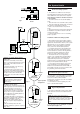
5.0 Installation 5.1 Initial Preparation 1. Unpack contents of carton. 2. Remove the lower door panel from the outer case. Remove the 2 screws holding the outer case to the combustion box. 3. Place the ready assembled outer case in a safe place until required. 4. Release the R clip from the top latch securing the combustion box to the back plate and release both latches (Fig. 15). 5. Lift and remove the combustion box from the back plate (Fig. 16). Place the combustion box on its back.
5.0 Installation 5.2 Fan Outlet Restrictor Rear Flue only up to 500mm (195/8 in) 1. Release the four latches holding the combustion box door (Fig 18). Remove the combustion box door by pulling forward (Fig. 17). Fig. 18 Fig. 19 2. Release the 5-pin electrical plug connecting the pressure switch and fan (Fig. 19). Withdraw the fan assembly by pulling forwards from the top edge (Fig. 17). Combustion Box Door 3.
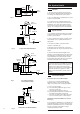
5.0 Installation 5.3 Position the Boiler 1. Choose a suitable position for the boiler making necessary allowances for the minimum clearances required (see page 10). 2. Hold the wall template against the wall at the required boiler location. Ensure that the top of the template is level (Fig. 22). Fig. 22 3. The template represents the outer limits of the appliance plus the required minimum side clearance. 4.
5.0 Installation Wall Thickness 5.5 Rear Flue Preparation Wall thickness 285mm - 500mm (115/16 - 193/8) go to section 5.6. Fig. 24 Wall thickness 100mm - 284mm (4 in - 113/16 in). Waste If the wall thickness is less than 285mm (113/16 in), it will be necessary to cut the components of the flue to the appropriate size. Wall Thickness 1. Measure the wall thickness (Fig. 24). Mark this dimension on the Flue Duct from the flared end and cut the waste off the plain end (Fig. 25). Flue Duct Fig.
5.0 Installation Blanking Cap 5.6 Assembly of Rear Flue 1. Remove the rear air box blanking plate from the back plate by releasing the three screws (Fig. 30). 2. Remove the blanking cap at the rear of the turret, by pushing and turning anti-clockwise to release the bayonet fitting (Fig. 30). 3. Locate the flared end of the flue duct over the bayonet fitting on the turret, taking care not to damage the 'O' ring. Lock the flue duct in place by pressing in and turning clockwise (Fig. 31).
5.0 Installation 5.7 Fitting the Back Plate 1. Engage the assembly into the hole previously cut in the wall and slide in place (Fig. 34). 2. Secure the assembly to the wall at the previously drilled anchorage points with suitable screws (Fig. 34). Before finally tightening the screws, check that the assembly is level. 3. Make good between the wall and the air duct outside the building if the internal fitting kit has not been used (Fig. 35). 4.
Maximum lengths for side flues using the standard telescopic flue kit 410mm (30, 40, 50) 410mm (30, 40, 50) 355mm (60, 70, 80) 355mm (60, 70, 80) 5.0 Installation 5.8 Left or Right Flue Concentric flue kits are available to allow 3 metres horizontal and 4 metres vertical flueing. Twin flue at 80mm diameter will allow up to 15 metres vertical flueing.
Wall Thickness 5.0 Installation 5.9 X 1. For both Left and Right Hand Flue - Measure the distance from the wall to the nearest line marked from the template. This will be known as dimension X (Fig. 45). Fig. 46 Fig. 45 Side Flue Preparation Total Flue Length Wall Thickness X 2. Measure the thickness of the wall from the inside. This will be known as Wall Thickness (Fig 46). 90mm (30, 40, 50) 145mm (60, 70, 80) 3.
5.0 Installation 5.10 Fitting the Flue and Back Plate 1. NOTE: There are two options for fitting the flue and back plate they are: Method A - Fitting the flue and back plate as an assembly (usually used where there are no side clearance problems). Blanking Cap Air Box Blanking Plate Turret Fig. 54 Method B - Pre-fitting the flue through the wall, fitting the back plate to its position on the wall and then connecting the two together (usually used where side clearances are restrictive). Fig. 53 5.
5.0 Installation 5.11 Method A (Cont) 7. Engage the assembly into the hole previously cut in the wall and slide into place. 8. Secure the assembly to the wall at the previously drilled anchorage points with suitable screws. Before finally tightening the screws, check that the assembly is level (Fig. 57). 9. Make good between the wall and the air duct inside and outside the building if the internal fitting kit has not been used (Fig. 58). 10.
5.0 Installation 5.12 Method B 1. Remove the left or right hand air box blanking plate, as appropriate, from the back plate air box by releasing the three screws (Fig. 61). Blanking Cap Air Box Blanking Plate Turret Fig. 62 2. Rotate the turret to face the selected opening (Fig. 62) and remove the side blanking cap by pushing in and turning anti-clockwise to release the bayonet fitting (Fig. 61). 3.
5.0 Installation 5.13 Terminal Guard 1. When codes of practice dictate the use of terminal guards, they can be obtained from most plumbers and builders merchants nationwide. 2. When ordering a terminal guard, quote the appliance name and model number. 3. There must be a clearance of at least 50mm between any part of the terminal and the guard. 5.14 Fitting a Terminal Guard (Fig. 68) 1. Position the guard over the terminal on the outside wall. Ensure the guard is equally spaced about the terminal.
5.0 Installation 5.15 Wall Thickness Internal Fitting Kit 1. A internal fitting kit (available from merchants, quote Baxi Part No. 236441BAX) is suitable for walls between 100mm (4in) and 285mm (113/16in) in thickness. 2. TO INSTALL THE KIT - Mark the flue hole centre as described in section 5.4 or 5.8. Cut a hole in the masonry approximately 117mm (45/8 in) diameter for the internal fitting kit. The use of a core drill is recommended.
5.0 Installation 5.15 Fig. 72 Internal Fitting Kit (Cont) 6. Refit the end piece to the liner and open out to the thickness of the wall. Seal the two pieces together using the tape provided with the kit (Fig 72). 7. Slide the assembled wall liner into the hole in the wall until the tags stop against the inner wall with the seam of the liner uppermost. Mark the positions of the holes in the tags on the wall and then rotate liner so that tags reveal marks (Fig. 73). 8.
5.0 Installation 5.16 Fitting the Combustion Box 1. Offer up the combustion box to the back plate and locate the rear bottom edge of the combustion box onto the self locating support at the base of the wall plate (Fig. 77). 2. Swing the top of the combustion box backwards against the top air box (Fig. 78). Fig. 78 Fig. 77 Fig. 79 28 3. Engage the two retaining latches and secure with the 'R' clip previously removed (Fig. 79).
5.0 Installation Fan 5.
5.0 Installation 5.18 Making the Electrical Connections 1. Remove the cover from the control box by removing the 2 screws (Fig. 80). 2. Slide the box forward for easier access. 3. The terminal strips may be removed by carefully pulling them forward. Connect the supply cable and the pump cable to the terminal strips (Fig. 82). IMPORTANT - When installing in conjunction with a thermal store or heat store please refer to the store manufacturers installation instructions when wiring the boiler. 4.
5.0 Installation 5.19 Water Connections 1. The boiler has two side water connections, the top connection being FLOW and the bottom connection being RETURN (Fig. 83). 2. It is essential that FLOW and RETURN pipes are connected to the correct fittings. 3. The top flow connection incorporates the boiler thermostat and overheat thermostat (Fig. 85). Fig. 83 4. A copper elbow, compression nut and olive are provided in the kit for the return connection.
6.0 Commissioning the Appliance 6.1 Commissioning the Appliance 1. Flush the whole system in accordance with BS 5793 (see Section 3.1 Water Circulating Systems). Check for water leaks. 2. Purge away air from the supply pipe at the gas service cock. (BS 6891) (Fig. 87). 3. Ensure that the electrical supply is isolated. 4. Check the electrical supply for earth continuity, polarity, short circuit and resistance to earth. Fig. 87 5.
6.0 Commissioning the Appliance Model kW Input P Btu/h Setting Pressure mbar in wg 6.1 Commissioning the Appliance (Cont) 30 10.99 37, 500 16.0 + 0.5 6.4 + 0.2 1. The burner pressure is factory set. 40 14.65 50, 000 16.0 + 0.5 6.4 + 0.2 50 18.32 62, 500 16.0 + 0.5 6.4 + 0.2 60 21.98 75, 000 16.0 + 0.5 6.4 + 0.2 2. From the table opposite check that the main burner pressure is correct after the appliance has been running for 10 minutes.
7.0 Fitting the Outercase 7.1 Fitting the Outercase 1. The warning label may be removed unless the boiler is to be fitted within a cupboard. Fig. 91 Infill Panel 2. Taking the ready assembled outercase, the front door of which has already been removed, proceed as follows: 3. If the appliance is flued to the left or to the right, remove the relevant infill panel by removing the retaining clips and fixing screws (Fig. 91). 4. Offer the outer case up to the hooks on the top of the back plate (Fig. 93). 5.
8.0 Overheat Cut-off Device 1 8.1 Operation 1. The overheat cut-off device is of the manual reset type and therefore it is important that the user knows how to reset the control should it ever cut out. 2 NOTE: Cut-out is indicated by illumination of the neon light on the control box. 2. Remove the lower door panel by following the sequence of diagrams (Fig 95). 3. To reset the boiler - Turn the boiler thermostat control knob fully anti-clockwise to the OFF position marked ‘0’ (Fig. 96).
9.0 Annual Servicing 1 9.1 Dismantling the Boiler 1. To ensure its continued safe and efficient operation, it is important that the appliance is regularly serviced. (For location of British Gas service test point see Changing Components section of these instructions). 2 2. Before servicing the boiler please read Section 1.3 Important Information. Fig. 98 3. After servicing, complete the relevant section of the “Benchmark” Installation, Commissioning and Service Record Log Book.
9.0 Annual Servicing Baffle Retension Clip 9.2 Fig. 102 Cleaning the Combustion Box 1. Remove the burner assembly by pulling it forward (Fig. 103). 2. Lightly brush any dirt from the top of the burner blades and ensure that the ports are free from obstruction. Baffles 3. Remove the baffle retension clip (Fig. 102). 4. Lift the baffles out of the heat exchanger (Fig. 103). 9.3 Cleaning the Heat Exchanger 1. The heat exchanger may be cleaned by insertion of a thin metal strip e.g.
10.0 1 10.1 Changing Components Changing Components 1. When changing components ensure that the gas and electrical supplies are isolated before the work is started. 2. Before changing any components please read Section 1.3 Important Information. 2 Fig. 109 4. Remove the outer case from the boiler by unscrewing the two screws and lift the case clear (Fig 109). British Gas Service Test Point. 3 3. Remove the outer case lower door panel (Fig. 108). For use by B.G. Personnel only 10.
British Gas Service Test Point. 10.0 For use by B.G. Personnel only 10.3 Changing Components Ignition Electrode (Fig. 114) 1. Disconnect the spark electrode lead at the electrode. 2. Unscrew the electrode from the manifold and withdraw the electrode. 3. Replace the new electrode in reverse order, ensuring that the sleeving is pushed over the end of the electrode. 10.4 Gas Valve (Fig. 115) 1. Disconnect the inlet gas cock union. Electrode 2.
10.0 10.7 Changing Components Changing Components (Cont) 1. To change Fan - Pressure Switch - Burner Burner Injector - Pilot Burner Injector - Gas Manifold, proceed as follows:Fig. 119 2. Release the four latches holding the combustion box door (Fig. 118). Remove the combustion box door by pulling forward (Fig. 120). 3. Release the 5-pin electrical plug connecting the pressure switch and fan (Fig. 119). Withdraw the fan assembly by pulling forwards from the top edge (Fig. 120). Fig. 118 10.8 Fan (Fig.
10.0 Changing Components 10.10 Burner (Fig. 124) 1. Remove the burner assembly by pulling it forward. 2. Fit new burner and re-assemble all components in reverse order of dismantling. 10.11 Burner Injector (Fig. 125) Fig. 124 1. Release and remove the burner injector which is screwed into the burner feed manifold. 2. Fit the new burner injector ensuring that the copper washer is in position. Tighten the injector fully. 3. Re-assemble all components in reverse order. 10.12 Pilot Burner Injector (Fig.
11.0 Before starting FAULT FINDING carry out preliminary electrical system checks i.e. Earth Continuity, Polarity, Short Circuit and Resistance to Earth.
11.
12.0 12.1 59 Short Parts List Short Parts List 53 Key No Description Model G.C.
13.
13.
Baxi UK Limited manufacture a comprehensive range of products for the domestic heating market Gas Central Heating Boilers (Wall, Floor and Fireside models). Independent Gas Fires. Renewal Firefronts. Gas Wall Heaters. Solid Fuel Fires. If you require information on any of these products, please write to the Sales Department.
Comp No 5106276 - Iss 1 - 11/01 After Sales Service 08706 096 096 Technical Enquiries 08706 049 049 Baxi UK Limited Brownedge Road Bamber Bridge Preston Lancashire PR5 6SN www.baxi.