Please leave these instructions with the user Baxi Bermuda Inset 3 Super Fireside Gas Central Heating Units Installation and Servicing Instructions TS, BS, KS & SC Super FS, BB, CB & BC Super
Natural Gas Codes of Practice, most recent version should be used Baxi Bermuda Inset 3 BS Super G.C.No. 37 075 56 Baxi Bermuda Inset 3 TS Super G.C.No. 37 075 57 Baxi Bermuda Inset 3 KS Super G.C.No. 37 075 54 Baxi Bermuda Inset 3 FS Super G.C.No. 37 075 55 Baxi Bermuda Inset 3 BB Super G.C.No. 37 075 62 Baxi Bermuda Inset 3 CB Super G.C.No. 37 075 63 Baxi Bermuda Inset 3 SC Super G.C.No. 37 075 64 Baxi Bermuda Inset 3 BC Super G.C.No.
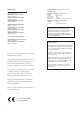
Contents Section Page 1.0 Introduction 4 2.0 Technical Data 5 3.0 Site Requirements 6 4.0 Electrical 8 5.0 Installation 9 6.0 Commissioning the Fire 13 7.0 Arranging the Coals 14 8.0 Checking for Spillage 16 9.0 Annual Servicing 18 10.0 Changing Components 21 11.0 Fault Finding 27 12.0 Flow Charts 28 13.
1.0 Introduction 1.1 Green Power ON Indicator Description 1. Your Baxi Bermuda Inset 3 Super is a central heating boiler combined with a gas fire. The firefront is of the Decorative Fuel Effect type and incorporates an optional illumination effect for use when the fire is off. The boiler will provide heating for the rest of the house and also domestic hot water if required. The boiler and fire are independently controlled. Boiler Thermostat Knob 2.
2.0 Technical Data Notice Bermuda Inset 3 TS, BS, FS, KS Super Bermuda Inset 3 BB, CB, SC, BC Super Discolouration of wall surfaces The fire is set for Gas Type G20 at 20mbar. Most heating appliances generate warm air convection currents and transfer heat to any wall surface against which they are situated.
460mm Min 560mm Max 3.0 Site Requirements 3.1 Fireplace Opening 560mm Min 590mm Max 1. The principal site requirements are determined by the boiler unit, but the following details are essential for the correct installation of the fire unit: Fireplace Opening (Fig. 2): Height: 560mm (22in) min 590mm (2315/64in) max Width: 460mm (18in) min 560mm (22in) max Fireplace Opening Fig. 2 625mm 625mm Surround and Non-Combustible Area Fig. 3 NOTE: The wall or surround behind the fire must be non-combustible.
3.0 Site Requirements 3.3 Ventilation 1. Ventilation air supply should be in accordance with the relevant standards. In GB this is BS 5440 Pt 2. In IE this is the current edition of I.S. 813 “Domestic Gas Installations”. The permanent ventilation area size requirements are as shown: 12.42in2 80.1cm2 2. The permanent vent may be directly into the room containing the appliance. The vent may also be sited in another (not a bedroom, toilet, bathroom or kitchen) room provided an interconnecting vent is used.
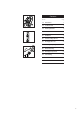
4.0 Electrical 4.1 Electrical Supply Wiring Key 1. Electricity is supplied to the fire unit via the plug and cable assembly provided with the fire. b - Blue br - Brown 2. The cable must be connected to the 4 pin plug and socket on the boiler. NOTE: The method of connection to the electrical supply must facilitate complete electrical isolation of the appliance.
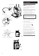
5.0 Installation 5.1 4 Pin Electrical Plug Initial Preparation 1. Unpack the fire unit from the carton. The coal bed and fender assemblies are packed in individual boxes within the main carton and should be left in these until required. Fig. 6 2. Remove the instructions and other literature from the combustion box together with the contents kit and glass pack. 5.2 3 Pin Electrical Plug Fig.
1.0 Introduction 4 Pin Electrical Plug 5.3 Making the Electrical Connection (continued) (50/5 model) 1. Take the 3 pin plug and lead assembly from the gas fire contents kit. 2. Remove the 4 pin electrical plug from the boiler (Figs.10b), remove the cover from the 4 pin plug and undo the cable clamps (Fig. 10d). Fig. 10b 3. Route the mains inlet cable under the boiler base through the cutouts (Fig. 10c).
5.0 Installation Fig. 11 5.4 Fitting the Fire Fire Surround Trim 1. Remove the fire surround trim from its poly bag (Fig. 11). The fire surround should be handled with care. Control Panel Assembly Bottom Lug 2.
5.0 Installation Electrical Supply From Boiler Base 5.4 Fitting the Fire (continued) 7. Fit the fire gas supply pipe at the motorised valve inlet (Fig. 18). 8. Fit the fire gas supply pipe to the gas service cock on the right hand side of the boiler base ensuring gas soundness is done at both connections on the gas supply pipe (Fig. 19). Control Box Fig. 17 9. Connect the electrical supply to the fire from the boiler (Fig. 17). 10.
6.0 Commissioning the Fire 6.1 Pressure Test Point Sealing Screw Commissioning the Fire 1. Turn on the main gas and electrical supply and press the button (Fig. 24) to check that the illumination effect operates. 2. Turn the gas service cock to the fire and boiler on position as shown, then purge according to in GB BS 6891 and in IE the current edition of I.S. 813 “Domestic Gas Installations”. (Fig. 23). 3. Check for gas soundness from the gas service cock to the fire inlet connection. Fig. 22 4.
7.0 Arranging the Coals Side Cheek Location Stop 7.1 Arranging the Coals It is important that all the coals are used and arranged as shown in order to achieve the desired flame picture. Fig. 25 1. Remove the loose coals, side cheeks, rear and front coals from their protective packaging and place them on a newspaper or similar to prevent soiling furnishings. Rear Coal Side Support Ledges Combustion Box Base Front Lip CAUTION: The coals are extremely fragile and must be handled accordingly.
7.0 Arranging the Coals Finial Fender Fender 7.1 Arranging the Coals (cont) 7. At this point it is necessary to fit the fender assembly. 8. Remove the fender from its packing (Fig. 30) (on FS, BB, CB, BC models screw the finials to the fender assembly). 9. Remove the controls access door from the fender assembly (Fig. 30). Controls Access Door Fig. 30 Controls Access Door FS, BB, CB & BC model Fender Assembly 10. Hook the fender into the sides of the combustion box (Fig. 31). 11.
8.0 Checking for Spillage 8.1 Checking for Spillage CAUTION - Whilst checking for spillage care must be taken to avoid touching hot panels. 1. Before checking for spillage the worst likely operating environment for the appliance must be created. To do this, close all doors and windows in the room and operate any ceiling or extractor fans that may be present, on the wall or within other appliances.
8.0 Checking for Spillage 8.4 Captive Nut Completion 1. Take the black painted extension piece, captive nut and screw from the fire contents kit. Door Shield 2. Fit the captive nut to the rear edge of the door shield, over the hole (Fig. 34). 3. Slide the extension piece between the door shield and the casting, ensuring the location hole locates over the pip on the door shield (Fig. 36). Fig. 34 4. Secure the extension piece to the door shield using the black screw (Fig. 37). 5.
9.0 Annual Servicing 9.1 Annual Servicing IMPORTANT: It is possible that some soot may be deposited on the coals after use. This is acceptable providing it is not allowed to accumulate. Gas Service Cock CAUTION: The coals are extremely fragile and must be handled accordingly. Gloves should be worn and any inhalation of the dust should be avoided. Keep the coals away from children at all times. Never use coals other than those originally supplied or Genuine Baxi Spare Parts.
9.0 Annual Servicing 9.2 Preparation (Cont) 8. Slacken the two screws inside the flue spigot (Fig. 46). Boiler Hood 9. Disconnect the electrical plug from the socket attached to the control box (Fig. 47). Flue Spigot 10. Slide the fire combustion box forward to disengage it from the flue spigot and lift away (Fig. 48) taking care not to snag any electrical wiring. Fig. 46 9.3 Fig. 48 Cleaning the Burner & Injectors 1.
9.0 Annual Servicing 9.5 Firebed Base Panel Cleaning the Combustion Box & Coals 1. Remove any deposits from the firebed base panel (Fig. 52). Burner 2. If necessary the coals can be cleaned with a very soft brush, and can be retouched using the black stain available direct from Baxi or from your local Baxi Spares Stockist. Quote Part No 043224 when ordering. Fig. 52 3. Refit the burner to the controls mounting plate (Fig. 53). Fig. 53 Retaining Screw 9.6 Replacing the Fire 1.
10.0 10.1 Changing Components Changing Components WARNING: Isolate the gas and electricity supplies to the boiler and fire unit before changing any components. Fig. 58 1. Lift the controls access door away from the fender assembly (Fig. 59). 2. Turn off the gas supply at the service cock (Fig. 60). 3. Carefully remove all the loose coals, side cheeks, rear and front coals (Fig. 58). CAUTION: The coals are extremely fragile and must be handled accordingly.
10.0 Boiler Hood 10.1 Changing Components Changing Components (continued) 9. Remove the two screws retaining the sides of the fire combustion box to the fire base tray (Fig. 67). Flue Spigot 10. Remove the two screws inside the flue spigot (Fig. 65). Fig. 65 11. Disconnect the electrical plug from the socket (Fig. 66). 12. Slide the fire combustion box forward to disengage it from the flue spigot and lift away (Fig. 64) taking care not to snag any electrical wiring. Control Box Fig. 64 Fig. 66 Fig.
10.0 10.3 Control Box Heat Shield 1. Disconnect the electrode lead from the electrode (Fig. 72) and the motorised gas valve leads from the control box (Fig. 71). Fig. 70 2. Undo the thermocouple nut from the front of the motorised gas valve and disconnect the pilot feed pipe from the valve and pilot/A.S.D. assembly (Figs. 72 & 73). Thermocouple Interrupter Leads Motorised Gas Valve Leads Pilot/A.S.D. Assembly NOTE: The thermocouple cannot be changed as an individual component.
10.0 Changing Components 10.4 Control Box Heat Shield Control Box 1. Disconnect the earth point. Heat Shield Retaining Screw 2. Remove the control box heat shield retaining screw and place the shield to one side (Fig. 74). 3. Disconnect all of the wiring connections from the control box taking note of their positions (Fig. 75). Control Box 4. Slacken the rear control box retaining screw. Fig. 74 Electrode Lead 5. Undo the front retaining screw and remove the control box (Fig. 76).
10.0 Changing Components Fire Surround Trim 10.6 Control Panel 1. Disconnect the control panel connector from the front of the valve bracket (Fig. 79). 2. Lift the surround trim away from combustion box (Fig. 78). 3. Remove the cable clamp which secures the control panel cable (Fig. 80). 4. Remove the two control panel securing nuts and remove the panel (Fig. 80). 5. Fit the new control panel taking care not to overtighten the securing nuts and reassemble in reverse order. Fire Surround Trim Fig.
Glass Retaining Assembly 10.0 Changing Components 10.7 Bulbs IMPORTANT: Only replace the bulb/s with a 12V 20W halogen capsule bulb available at most DIY outlets, specialist electrical stores or through Baxi. 1. Remove the coals, placing them on a newspaper or similar to prevent soiling furnishings. 2. Lift out the glass retaining assembly (Fig. 81). Fig. 81 3. Remove the bulb by pulling out from the ceramic bulb holder to disengage the pins (Fig. 82). 4. Fit the replacement bulb in reverse order.
11.0 Fault finding Before starting Fault Finding carry out preliminary electrical system checks i.e. Earth Continuity, Polarity, Short Circuit and Resistance to Earth.
Sequence of Automatic Control System IGNITION Press ON button & hold for a minimum of 3 seconds System is reset ON neon activated ON neon deactivated Start gas to pilot start spark Gas closed Is ON button pressed for 3-4 sec? NO 12.
12.
13.0 Short parts list Short Parts List 20 19 13 Key G.C. No. No. Description Manufacturers Part No.
Baxi manufacture a comprehensive range of products for the domestic heating market Gas Central Heating Boilers (Wall, Floor and Fireside models). Independent Gas Fires. Renewal Firefronts. Gas Wall Heaters. Solid Fuel Fires. If you require information on any of these products, please write to the Sales Department.
BAXI POTTERTON Brownedge Road Bamber Bridge Preston Lancashire PR5 6SN After Sales Service 08706 096 096 Technical Enquiries 08706 049 049 www.baxi.co.