Owner's Manual [ S/N LABEL HERE ] Document # BW-WT4-2DOC
BAYweb Thermostat Model BW-WT2 Owner's Manual Copyright © 2009-2010 Bay Controls, LLC Part Number: BW-WT4-2DOC Revision: 1.1 November 5, 2010 BAYweb is a registered trademark of Bay Controls, LLC. Patent pending technologies are used in the BAYweb Thermostat.
Table of Contents Introduction.............................................................................................................1 About This Manual..................................................................................................1 Safety Precautions..............................................................................................1 Limited Warranty.................................................................................................3 Limitation on Liability..
Introduction Thank you for purchasing the BAYweb Thermostat. You now have one of the most advanced Heating, Ventilating, and Air Conditioning (HVAC) control systems available today. This thermostat is easily installed by home owners or HVAC professionals. It can be used to replace an existing thermostat or for installation with new heating or cooling equipment.
Bay Controls, LLC. expressly disclaims responsibility or liability for any injury or damage caused by failure to observe specified or other common safety precautions or failure to exercise ordinary caution, common sense, and due care required in installing and operating the thermostat even though not specified herein. The alert message shown here appears throughout this manual to indicate those situations and times when special care is necessary to prevent equipment damage or personal injury.
Limited Warranty Subject to the limitations contained below, and except as otherwise expressly provided herein, Seller warrants to the Buyer that all tangible articles supplied by Seller or services provided by Seller will be free of defects in materials or workmanship under normal use and care until the expiration of the applicable warranty period. Goods are warranted for five (5) years from the date of purchase.
Installation Overview Installing the thermostat is a relatively simple process and typically takes from 10 to 30 minutes to complete. You should consider the current outdoor temperature. If unexpected problems occur, you do not want to risk freezing or overheating, while you are sorting the problem out. You will need screwdrivers, a wire stripper/cutter, and a drill for installing the wall anchors to complete the installation. A volt/ohm meter can be helpful for troubleshooting but is not required.
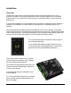
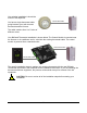
Your existing installation is should be similar to this depiction. Thermostat Cable You have a single thermostat cable going between your wall mounted thermostat and the furnace. The cable contains from 2 to 5 wires of different colors. Your BAYweb Thermostat installation is shown below. The Control Module is mounted near the furnace or air conditioner and is wired into the existing thermostat cable. The control module is powered from a standard outlet.
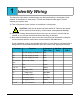
1 Identify Wiring The objective of this step is to identify how your thermostat wiring is connected to your furnace, air conditioner, or heat pump. This will also determine what type of control scheme your system uses. A) Turn off all power to your furnace, air conditioner, or heat pump. ! CAUTION: Verify that all power has been turned off. Failure to turn power off may result in personal injury, electric shock, and equipment damage.
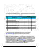
D) If you do not have a wire attached to terminal “C” or “X”, you will need to use the included power supply to power the thermostat. The power supply plugs into a standard 120VAC outlet and to a connector on the control module. E) The following table shows what terminals are used by the different control methods. Determine which control method your system is using by matching which terminals are connected to your wiring. Circle the number of the system type that you have.
2 Install Control Module A) Find your thermostat cable where it goes into the furnace, air conditioner, or heat pump. This is the same cable identified in Step 1 and should be the same color and thickness as that cable. ! CAUTION: There may be other cables of similar color connecting other devices such as a humidifier. Be sure to use the cable that runs back to your thermostat and not one that is connected to another device.
E) Connect the wiring going to the furnace, air conditioner, or heat pump: Attach the wires in the cable coming from the furnace to the terminals on the RIGHT side of the control module labeled "Furnace/AC". Be sure to match the wire color and terminal designation as identified in Step 1. NOTE: If your system uses separate Rh and Rc wires, be sure to remove the jumper wire between the Rh and Rc terminals.
3 Install Thermostat Keypad A) Remove the wires from your existing thermostat, taking care that the wires do not fall back into the wall. B) Remove the existing thermostat and any associated mounting hardware. C) Fill in any holes from the previous thermostat mounting and paint the wall if needed. D) Hold the Thermostat Keypad in the desired position and mark the location of the top mounting screw. Locate the bottom mounting screw 3 ½ inches below the top screw location.
Wall mounting location with the existing thermostat cable prepared to install the new Thermostat Keypad. If the ends of the existing wiring are worn or broken. Cut off the ends and strip about ¼ inch of insulation from the end of each wire. Now is a good time to touch up the paint if needed. Locate and install the wall anchors and mounting screws as shown, and described above. Connect the Thermostat Keypad to your thermostat wiring as shown.
4 Connect to the Internet The BAYweb Thermostat is factory configured for system type 3, conventional one heat/one cool. This will also work for system types 1 and 2. If you have a multistage furnace, air conditioner, or heat pump, you will need to connect the thermostat to the Internet and configure it for the type of system that you have prior to use. A) Connect the Control Module to the Internet.
5 Configure the Thermostat The thermostat is configured using the BAYweb portal. The following steps will guide you through setting up your own personal web portal and configuring the thermostat. If you have already setup your own portal, simply click on the “My Devices” link to add the thermostat. A) Go to the BAYweb site by entering www.bayweb.com in the address bar of your web browser. B) Click on the “Create an account” link in the login box. C) Enter the requested information.
6 Test Operation A) Turn the power back on to the furnace, air conditioner, or heat pump. B) Verify that the “Power” and “Thermostat” lights are illuminated on the control module. If either one is not on, refer to the Troubleshooting section of this manual. C) Verify that the Thermostat Keypad is showing the temperature. If it is showing an “E” with a number, this is an error code. Refer to the Troubleshooting section. D) Test FAN operation: Press the keypad near the “FAN” label.
Operation Using the Thermostat Keypad The Thermostat Keypad shows the current temperature, set point and modes, and allows you to manually control your furnace and air conditioner. Indicators show which modes are selected Press to select HEAT mode. If selected, press again to turn OFF. Press to select COOL mode. If selected, press again to turn OFF. Press once to show the current set point. Press again to change. Current Temperature Press to change HOLD mode.
Using Your Mobile Phone Once you have setup your personalized web portal, you can also use most any mobile phone that has web access to remotely access your thermostat and other web devices. To access the mobile web portal, enter the following address in your mobile phone browser: www.bayweb.com/mobile.
Occupancy sensing with pets in the home is accomplished by masking off the lower part of the sensing lens. You should locate your sensors in high-traffic areas of your house so that they will be most likely to sense when people are present. The sensors from Bay have a 10+ foot range and will sense people as they pass in front of the sensor. We have found that locating them at about chest height or higher works well. Once you have installed your occupancy sensors login to the web portal to enable them.
Alerting Alerting is a powerful feature that enables you, and others you designate, to be notified of the following events: • Problems with your thermostat and HVAC system. • Excessive heating or cooling energy usage. • Intrusion. • Loss of Internet connectivity. • Other problems or alerts with anything else you choose to connect to the control module (wired or wireless). Alerting provides many of the features of a traditional alarm system without the monthly fee.
Reference Thermostat Keypad The Thermostat Keypad module senses the current temperature and provides an interface for manual control. Normally the displayed number (68 in this case) indicates the current temperature. To change the set point, press the up or down arrows. The display will switch to the current set point. Note that a decimal point is displayed while showing the set point. The display will automatically revert to the current temperature after a few seconds if no keys are pressed.
Code Meaning E1 Indicates that the thermostat keypad is not communicating with the control module.
Thermostat Connector This connector is used to connect the Thermostat Keypad module to the Control Module. This is a proprietary interface and can only be used with the specified modules. The Red and White terminals supply power (3.3 VDC), the Green and Yellow terminals utilize a proprietary communications protocol. Furnace/AC Connector This connector is wired to your furnace and/or air conditioner, or heat pump, and provides control of your equipment.
Indicator Description Fan Indicates when the thermostat is signaling the furnace, air conditioner, or heat pump to turn on the fan. Reverse Indicates that the thermostat is signaling the heat pump to activate the reversing valve. The “B” terminal is normally closed, it supplies power when the Rev LED is off. The “O” terminal is normally open, it supplies power when the Rev LED is illuminated. The use of the “O” and “B” terminals may vary by manufacturer of the heat pump.
Solutions to Problems Problem No Control Module power indication. Keypad is dark, no power at keypad. Fan control does not function. Heat does not function. Solution ✔ Check for 24VAC power between terminals “R” and “C” on the Furnace/AC connector, or if using the power supply, check for power at the outlet. ✔ Unplug Alert input and Thermostat connectors, if power light comes on there is a short or improper connection on one or both of these connections. ✔ Contact support for replacement Control Module.
Problem Cool does not function. Solution ✔ Verify that the outside temperature is greater than 40º F. ✔ Verify that Cool mode is selected on the Thermostat Keypad. ✔ Verify that the set point is lower than the current temperature. ✔ Verify on the Control Module that the Cool light is ON. ✔ Check the red and yellow wires between the Furnace/AC connector on the Control Module and your Furnace/AC.
Problem Thermostat Keypad shows error code “E4”: Solution ✔ Check your Internet connection. ✔ Check your Internet wiring. The Internet connection was down for an ✔ Make sure you can browse the Internet extended period of time (It is unlikely that this using the thermostat network cable. is a problem with the thermostat). Thermostat Keypad shows error code “E5”: ✔ The thermostat can continue to operate. The non-volatile memory in the control ✔ Contact support to obtain a module has been lost or corrupted.
Obtaining Support Customer support is handled on line 24 hours per day, 7 days a week. Before requesting support, please review the Frequently Asked Questions and other resources available at www.bayweb.com. When contacting us for support, please provide your name, web portal user ID (if you have one), and thermostat serial number, located on the front cover of this manual and on the Control Module. Support email: support@bayweb.
Thermostat Connections The following table shows all standard thermostat terminals and associated functions.
Specifications Part Numbers: BW-WT2 (specify color) Thermostat Keypad: BW-T100 or BW-T110 (specify color) Control Module: BW-BCU4-2 Control Types: Single and multistage heat/cool, heat pump with aux heat Fan Control: Auto, On, auto with minimum circulation Set Points: 4 heat, 4 cool Schedule: 7 day, up to 48 periods per day, automatically adapts with occupancy sensing Control Features: Automatic changeover, compressor protection, set point limiting User Interface: Keypad with LED display and We