
Specifications


9031398 E3 Chassis Management Views
3-9
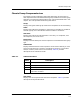
Chassis Group View
Chassis Group Components view
SPECTRUM has not detected a change since the start of the agent.
Administration State
Allows modification of the desired state of the component. Table 3-1 defines
the possible Administrative State values.
Max Sub-Components
Displays the potential number of sub-components that can be attached to this
component. A value of -1 indicates that no component information is available.
If this entry is itself a sub-component then this field displays a value of zero,
as though there were no sub-components attached.
Operational State
Displays the current operational state of the component. Table 3-2 defines the
possible Operational State values.
Num Sub-Components
Displays the actual number of sub-components currently attached to this
component. A value of -1 indicates that no component information is available.
If this entry is itself a sub-component then this field displays a value of zero,
as though there were no sub-components attached.
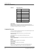
Component Store Table
Provides a list of the storage areas available on each component in the chassis.
Only components in the chassis that have manageable storage areas are
displayed in this list. Examples of storage areas include RAM (main memory),
FLASH, ROM, and EEPROM. Disk drives are not considered manageable
storage areas. Table 3-3 describes the information provided in this table.
Table 3-3. Component Store Table Fields
Field Description
Storage The index of the storage area on the component.
Storage Type The storage area type on the containing component.
Current Size (bytes) The current size of the storage area in bytes. A value of
zero means the storage area is not installed or not usable.
A value of -1 indicates that the size is unknown or
unavailable.
Content Version The version of the contents (i.e., the code or data) of the
storage area.