
Technical data

Installing and Operating BayStack ARN Routers
1-24
114200-D Rev 00
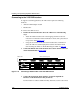
Connecting to the X.25 PAD Interface
To support X.25 PAD applications, the ARN router requires the following
hardware:
• ARN X.25 PAD adapter module
• Breakout box
To connect X.25 PAD services:
1.
Position the X.25 breakout box above the ARN in one of the following
ways:
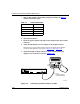
• Attach the rubber feet that came in the shipping container to the four
raised areas on the bottom of the breakout box chassis; then, place the box
on top of the ARN (Figure 1-18
).
• Using the screw holes on the sides of the breakout box, install the box
above the ARN in a standard equipment rack. For information about
rack-mounting the ARN, see “Rack-Mounting the ARN” on page 1-6
.
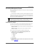
2.
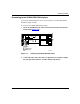
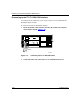
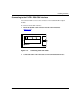
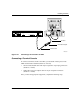
Connect the DB-60 cable on the breakout box to the X.25 PAD connector
on the installed module (Figure 1-18
).
Figure 1-18. Connecting a Breakout Box to the X.25 PAD Interface
3.
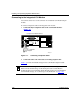
Connect the appropriate WAN cabling to each of the eight DB-25
interfaces on the breakout box that you will use.
For information on cables available from Bay Networks, see the Cable Guide.
ARN0088A
COM3 COM4 COM5
Serial
COM
TX
RX
RLSD
Run
Boot
Fail
Pwr
RPS
Fan
Base
Adapter1
Adapter2
Expansion
DCM
PCMCIA
BayStack Advanced Remote Node
RLSD3
RLSD4
RLSD5
1
2
Serial
Tx
Rx
Cl
Tx
Rx
Cl
10BaseT
AUI
Ethernet 1
10BaseT
AUI
Ethernet 2
X.25 PAD
DB-60 cable
DB-25 connector ports