
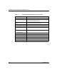
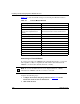
Technical data

Installing and Operating BayStack ARN/DC Routers
1-22
116273-B Rev 00
3.
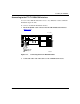
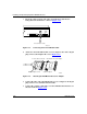
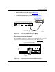
Insert the 9-pin receptacle end of the console/modem cable into the
back-panel Console interface connector (Figure 1-15)
.
Figure 1-15. Connecting the Console/Modem Cable
4.
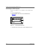
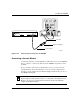
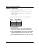
Attach one end of the null modem crossover adapter to the cable’s 25-pin
plug connector, then tighten the screws (Figure 1-16)
.
Figure 1-16. Attaching the Null Modem Crossover Adapter
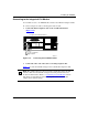
5.
Connect the other end of the null modem crossover adapter to the 25-pin
plug connector on a standard AT serial cable.
6.
Connect the complete cable unit to a serial communications interface on
the back of the PC (Figure 1-17)
.
Console Modem
Console/modem cable
ARN0083B
Null modem crossover adapter
Console cable connector
Screw receptacle
Rotate to tighten screw
AN0010A