
User manual


Installing and Operating BayStack ARN Routers
3-2 114200 Rev. A
LED Descriptions
LEDs on the ARN front and back panels provide information about how the ARN
is operating. The following sections describe the LEDs on the ARN base modules,
expansion modules, adapter modules, and the ARN back panel.
Base Module LEDs
The ARN base module LEDs include diagnostic LEDs and either Ethernet or
token ring interface LEDs.
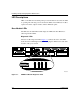
Diagnostic LEDs
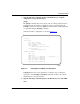
The base module diagnostic LEDs (F
igure 3-1) indicate the status of the ARN
itself. All of these LEDs light briefly when you plug the ARN into the wall outlet
and turn on the power switch.
Figure 3-1. ARN Base Module Diagnostic LEDs
Run
Boot
Fail
Pwr
RPS
Fan
Base
Adapter1
Adapter2
Expansion
DCM
PCMCIA
AUI
ARN0059A
COM3 COM4 COM5
COM
U
D
DD
B1
B2
RLSD
Run
Boot
Fail
Pwr
RPS
Fan
Base
Adapter1
Adapter2
Expansion
DCM
PCMCIA
BayStack Advanced Remote Node
RLSD3
RLSD4
RLSD5
1
2
Serial
Serial
ISDN BRI
withNT1
Tx
Rx
Cl
Tx
Rx
Cl
10BaseT
AUI
Ethernet 1
10BaseT
AUI
Ethernet 2