Start Here The NETGEAR Model FS308 Fast Ethernet Switch provides you with a lowcost, high-performance network solution for the home or small office. It is designed to support power users operating at either 10 megabits per second (Mbps) or 100 Mbps. Ethernet switches provide private, dedicated, 10 or 100 Mbps capacity to each connected PC/server or hub/workgroup segment.
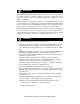
• Home and small office friendliness — Network ports located on the back of the hub so that cables are kept away from the desktop — Compact design to fit into small offices — Compliance with the Class B EMI standard so the switch will not interfere with your home appliances • 5-year warranty on hub unit (1-year warranty on power supply) Package Contents Model FS308 switch MODEL Auto 10/100 Mbps 8 PORT 10/100Mbps Fast Ethernet Switch Power Wall Mount Installation kit FS308 100 Link/Act.
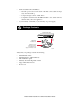
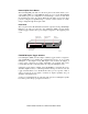
Product Illustration Power LED 100 Link/Act LEDs MODEL Auto 10/100 Mbps 8 PORT 10/100Mbps FS308 100 Link/Act. 10 Link/Act. FDX/Col. Fast Ethernet Switch Power 1 2 3 4 5 6 7 8 FDX/Col LEDs 10 Link/Act LEDs 8921FA Front Panel The front panel of the Model FS308 switch contains the following LEDs that correspond to each network port located on the back of the hub: 100 Mbps link/ activity (100 Link/Act), 10 Mbps link/activity (10 Link/Act), and full-duplex/ collision (FDX/Col).
Normal/Uplink Push Button The Normal/Uplink push button on the front panel of the switch allows you to select uplink (MDI) or normal (MDI-X) wiring for port 8 on the Model FS308 switch. These ports are configured for normal wiring to connect to a PC when the push button is in the out position. When the push button is pressed in, these ports are configured for uplink wiring to connect to another switch or to a hub, using a straight-through twisted pair cable.
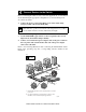
Applications The Model FS308 switch is designed to provide flexibility in configuring your network connections. Each switch can be used as a standalone device or can be used with 10 Mbps or 100 Mbps hubs or other interconnection devices in various configurations. The configuration examples in this section illustrate the integration of the switches in various network environments using other NETGEAR products.
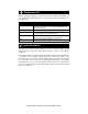
Prepare the Site Before you begin installing your switch, prepare the installation site. Make sure your operating environment meets the operating environment requirements of the equipment. Characteristic Requirement Temperature Ambient temperature between 0° and 40° C (32° and 104° F). No nearby heat sources such as direct sunlight, warm air exhausts, or heaters. Operating humidity Maximum relative humidity of 90%, noncondensing. Ventilation Minimum 2 inches (5.08 cm) on all sides for cooling.
Connect Devices to the Switch Before connecting the switch, be sure you review “Applications” for information about determining the appropriate configuration for your networking needs. To connect the switch: 1. Connect the devices to the 10/100 Mbps ports on the switch, using Category 5 UTP cable and an RJ-45 plug. Note: Ethernet specifications limit the cable length between your PC or server and the switch to 328 feet (100 meters) in length. 2. Set the Normal/Uplink push button. 3.
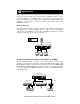
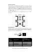
Twisted Pair Cables For two devices to communicate, the transmitter of each device must be connected to the receiver of the other device. The crossover function is usually implemented internally as part of the circuitry in the device. Most ports on switches and repeaters have media-dependent interfaces with crossover ports. These ports are referred to as MDI-X or normal ports. Computer and workstation adapter cards are usually media-dependent interface ports referred to as MDI or uplink ports.
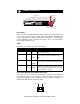
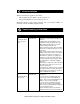
Verify Installation When power has been applied to the switch: • • The green Pwr (Power) LED on the front panel is on. The green Link LED on each connected port is on. When the switch is connected and operating, refer to the table in “LEDs” for information about the LEDs and their activity. Troubleshooting Information Symptom Cause Solution 100 Link/Act LED Port connection is or not functioning. 10 Link/Act LED is off on an active port.
Symptom Cause Solution 100 Link/Act LED Port is operating in is off when 10 Mbps mode. operating in a Fast Ethernet network. Make sure the adapter card is capable of 100 Mbps operation and set for 100 Mbps operation if it is not autosensing. 100 Link/Act LED Port is operating in or half-duplex mode. 10 Link/Act LED is on and bicolor FDX LED is off when operating in a Fast Ethernet network. Make sure the duplex switch on the Model FS308 Fast Ethernet Switch is set for fullduplex operation.
Technical Specifications General Specifications Model FS308 Fast Ethernet Switch Network Protocol and Standards Compatibility ISO/IEC 802-3 (ANSI/IEEE 802.3i) 10BASE-T Ethernet IEEE 802.3u, IEEE802.3x 100BASE-TX Fast Ethernet Data Rate 100 Mbps with 4B/5B encoding and MLT-3 physical interface for 100BASE-TX 10 Mbps differential Manchester encoded Interface RJ-45 connector for 10BASE-T or 100BASE-TX Ethernet interface Power Consumption Input Voltage (Power Adapter) 15.
© 1998 by NETGEAR, Inc. All rights reserved. Trademarks Bay Networks is a registered trademark of Bay Networks, Inc. NETGEAR is a trademark of Bay Networks, Inc. All other trademarks and registered trademarks are the property of their respective owners. Statement of Conditions In the interest of improving internal design, operational function, and/or reliability, NETGEAR reserves the right to make changes to the products described in this document without notice.
EN 55 022 Declaration of Conformance This is to certify that the NETGEAR Model FS308 Fast Ethernet Switch is shielded against the generation of radio interference in accordance with the application of Council Directive 89/336/ EEC, Article 4a. Conformity is declared by the application of EN 55 022 Class B (CISPR 22).
NETGEAR, Inc.