
- Bay Ethernet Switche User Manual

Introduction to the BayStack 303 and 304 Ethernet Switches
893-01010-A 1-3
Physical Description
This section provides descriptions of the components on the front panels of the
BayStack 303 and 304 Ethernet Switches.
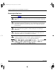
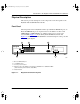
Front Panel
The front panels of these BayStack switches provide RJ-45 10BASE-T ports, an
RJ-45 10/100BASE-T port, an expansion slot for the addition of either a 10/
100BASE-TX or 100BASE-FX port, a DB-9 connector for a console, and
assorted LEDs. Figure
1-1 shows the BayStack 304 Ethernet Switch, and
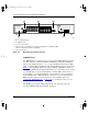
Figure
1-2 shows the BayStack 303 Ethernet switch. Descriptions of the ports and
LEDs follow the figures.
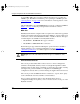
1 = One 10/100BASE-TX port
2 = 12 10BASE-T ports
3 = Console port connection∆
4 = Expansion slot for the addition of an optional 10/100BASE-TX or 100BASE-FX MDA
(switch should be powered down to install MDA)
5 = Status indicators
Figure 1-1. BayStack 304 switch front panel
304
Console
100BASE-TX
MDA
1357911
213 4 6 8 10 12
Power
100BASE-TX
Link
100
F Dx
1357911
24681012
899EB
1
4
32
5
89301010.BK Page 3 Tuesday, June 10, 1997 8:00 PM