Using the BayStack Ethernet Redundant Fiber Media Adapter Bay Networks, Inc.
© 1996 by Bay Networks, Inc. All rights reserved. Trademarks Bay Networks, BayStack, and Bay Networks Press are trademarks of Bay Networks, Inc. Other brand and product names are registered trademarks or trademarks of their respective holders. Statement of Conditions In the interest of improving internal design, operational function, and/or reliability, Bay Networks, Inc. reserves the right to make changes to the products described in this document without notice. Bay Networks, Inc.
Introduction This guide describes the Bay Networks 10BASE-FL RDN Media Adapter for the BayStack 10BASE-T Hubs and provides instructions for installing, connecting, and configuring the adapter in the hub. Each BayStack 10BASE-FL RDN Media Adapter consists of one optional 10BASE-FL port that provides flexible, redundant backbone connectivity and two diagnostic LEDs.
BayStack 10BASE-FL RDN Media Adapter The BayStack 10BASE-FL RDN Media Adapter is a modular 10BASE-FL port. The port is compatible with the IEEE 802.3 10BASE-FL specification for Ethernet running over 62.5/125 µm or 50/125 µm multimode fiber optic cable. 10BASE-FL (fiber link) asynchronous signaling is fully interoperable with fiber optic interrepeater link (FOIRL). Remote signaling and redundant links are also supported.
LEDs The BayStack 10BASE-FL RDN Media Adapter provides LEDs to indicate remote signaling and redundant link status. These LEDs are used in combination with the BayStack 10BASE-T Hub “Media Adapter” LED to indicate the status of the active and standby link. Table 1 describes the redundant 10BASE-FL media adapter LEDs. Table 1.
Table 2 describes the LED combinations of the hub “Media Adapter” LED and the redundant fiber media adapter LEDs. Table 2. LED status combinations Hub LED Rem Rdn Meaning Green Green Green Active link in a redundant port pair; link status is good, and remote link is good. Amber Green Green Standby link in a redundant pair; link status is good, and remote link is good.
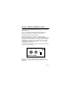
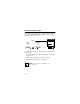
Redundant Enable Jumper Jumper JP1 is used to set the port to operate in the redundant port mode. The 10BASE-FL RDN Media Adapter is shipped with the redundant port mode set to off. Jumper 1 Default mode Redundant mode JP1 RDN EN JP1 RDN EN 6771 To set the port to operate in the redundant port mode, perform the following steps: • Locate the shunt covering the JP1 jumper pins on the media adapter board. • Gently remove the shunt from the two far left pins.
Redundant Links The BayStack 10BASE-FL RDN Media Adapter supports redundant links between Bay Networks BayStack Ethernet hubs, System 5000 hubs, and other Bay Networks hubs that support redundant links. If one fiber connection in a redundant pair breaks, the standby link automatically takes over in less than 10 microseconds. This redundant link feature allows you to build Ethernet dual-homing and mesh-type topologies. The port at both ends of the fiber connection must support Bay Networks remote signaling.
For a pair of ports to operate in redundant mode: • Enable the JP1 jumper for redundant port mode on both of the media adapters in the redundant port pair. For more information about this jumper, see “Redundant Enable Jumper” earlier in this guide. • Disable any redundant port mode on the port at the other end of each redundant link. A Rdn LED media adapter indicates redundant link status. For more information about this LED, see “LEDs” earlier in this guide.
Fiber Optic Cable Length Limitations The 10BASE-F standard permits you to use fiber optic cables up to 2000 meters long. However, the fiber connection must meet the following criteria: • Optical power budget (shown in Table 3) • Ethernet repeater rules For more information about simple rules for Ethernet network compliance, refer to Using the BayStack 10BASE-T Hubs. The optical power budget is shown in Table 3.
Table 4 lists the most common cable and connector combinations, assuming the maximum permitted attenuation with ST connectors. The table lists the maximum (total) distance allowed in the fiber connection. However, your fiber connection may have to be shorter to meet the optical power budget and Ethernet repeater rules. Table 4. 10BASE-FL cable and connector combinations 62.
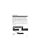
Installing a Media Adapter in a BayStack Hub The BayStack 10BASE-FL RDN Media Adapter is installed in a slot on the front of the BayStack 10BASE-T Hub. To install a media adapter, follow these steps: 1. Unplug the BayStack 10BASE-T Hub power cord from the AC power source. 2. Remove the filler panel from the media adapter slot on the front panel of the hub. 3. Install the media adapter into the media adapter slot. a.
6. Verify the installation for the media adapter. Observe for the installed media adapter that the respective Media Adapter LED on the front panel of the hub lights according to Table 5. Table 5. Media adapter status LEDs Hub media adapter 10BASE-FL RDN Media Adapter LEDs LEDs Green Link status is good, port not partitioned. Amber Link status is good, port is partitioned. Off Link status is bad or connection is not present.
Bay Networks, Inc. One-year Limited Hardware Warranty Bay Networks warrants this hardware product will be free from defects in material and workmanship for a period of one (1) year under normal operating conditions from the date of original purchase. Should you discover a defect in material or workmanship within this warranty period, Bay Networks will repair or replace the defective product when it is returned to Bay Networks, shipping prepaid.
Electromagnetic Emissions Meets requirements of: FCC Part 15, Class A Digital Devices VCCI Class 1 ITE EN 55 022 (CISPR 22, Class B) General License Vfg 243 (Class B) Compliance with the VCCI regulation is dependent upon the use of shielded AC power cables. The user is responsible for procuring the appropriate cables. Compliance with Class B regulations is dependent upon the use of shielded cables. The user is responsible for procuring the appropriate cables.