
- Bay Technical Associates, Inc. OWNER'S MANUAL DATA SWITCH/POWER CONTROL DS2-RPC DS4-RPC, DS71 DS71-MD2 DS74, DS73

DS-RPC OWNER’S MANUAL
CABLING
__________________________________________________________________________________________
15
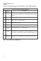
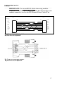
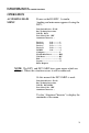
DS74 EIA-232 RJ-45 Pin/Signal Definition
Pin EIA-232
Signal
Description
1 Handshake
Out
(DTR) Line Driver Inactive State = Low: Used as a handshake line
to enable/disable the receiving of characters. –12V when port is not
selected unless programmed differently.
2 Gnd Signal ground
3 Handshake
Out
(RTS) Line Driver Inactive State = Low: –12V when port is not
selected unless programmed differently.
4 TX Out Transmit Data (data out)
5 RX In Receive Data (data in)
6 Handshake
In
(DSR) Handshake In. +12V when not used.
7 Gnd Signal ground
8 Handshake
In
(CTS) Used as a handshake line to enable/disable the receiving of
characters.
Table 3 DS74 PIN SIGNAL DEFINITION
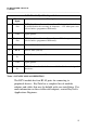
The DS74 module has four RJ-45 ports for connecting to
peripheral devices. BayTech has a complete line of modular
adapters and cables that may be helpful with your installation. For
more information on these cables and adapters, contact BayTech’s
Applications Engineers.