2012 Data Switch‐Remote Power Control (DS‐RPC) Copyright 2012 Bay Technical Associates, Inc 12/1/2012
Table of Contents COMPLIANCE STANDARD .............................................................................................................................................................. 4 INSTALLATION ......................................................................................................................................................................... 5 UNPACKING ......................................................................................................................
BAYTECH PRODUCT WARRANTY .................................................................................................................................................. 23 EXCEPTIONS ............................................................................................................................................................................................ 23 BAYTECH EXTENDED WARRANTY ............................................................................................................
ABOUT THIS DS‐RPC OWNER’S MANUAL This document provides information required for installing and operating your Bay Tech equipment. It should allow the user to connect to, power up, and access an applications menu where peripheral equipment can be controlled. We recommend reading this manual carefully, while placing special emphasis on correct cabling and configuration.
INSTALLATION Unpacking Compare the unit and serial number of the equipment you received to the packing slip located on the outside of the box. Inspect equipment carefully for damage that may have occurred in shipment. If there is damage to the equipment or if materials are missing, contact BayTech Customer Support at 228-563-7334 or call toll free inside the United States at 800-523-2702. At a minimum, you should receive the following: 1. DS-RPC series unit and/or DS modules. 2.
CAUTION: High-voltage surges and spikes can damage this equipment. To protect from such power surges and spikes, this unit must have a good earth ground or good power surge protection. ATTENTION: Les montées subites et les transitoires à haute tension peuvent endommager cet équipement. Pour se protéger contre de telles montées subites et transitoires de puissance, cette unité doit avoir une bonne protection rectifiée ou bonne de la terre de puissance de montée subite.
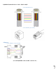
CABLING RJ45 Cable Control Module RJ-45 pin Signals EIA 232 Signal Pin Signal Direction 1 2 DTR GND Out 3 4 5 6 7 8 RTS TX RX DSR GND CTS Out Out In In In Description Handshake, Line Driver Inactive State = High: +12V when power is applied. Used as a handshake line to enable/disable the receiving of characters. Signal Ground Handshake, Line Driver Inactive State = High: +12 V when power is applied. Not used to enable/disable. Transmit (Data Out) Receive (Data In) Handshake In.
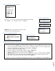
RJ08X007 Standard Rollover Cable – RJ45 to RJ45 Serial 2: RJ08X007 Pin out Serial 3: RJ45 Receptacle & Plug Adapters Serial 4: 9FRJ45PC-1 Adapter Pin Out Page 8 (Use with RJ08X007 Cable and B/C switch in “B”)
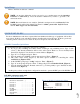
Serial Setup Refer to the Host module user’s manual NOTE: At any time during the session you need to go to another menu, use the Attention Character = semi-colon (;). Press the attention character key 5-times to get back to the main status menu. NOTE: Password feature is case sensitive. (Default is user/password is root/baytech). If the DS-RPC login is enabled, the default User Name is ‘admin’; password is ‘baytech’ lower case or ‘BTA’ upper case for older units.
Figure 3: DS2-RPC Menu Rev F0.15 DS-RPC Power Control (C) 1997 by BayTech Rev. F0.15 Circuit Breaker: On 1)...Outlet 1 2)...Outlet 2 3)...Outlet 3 4)...
Figure 9: Host Module Menu Module: Attention Character: ] Device A ................1 Device B ................2 Device C ................3 Device D ................4 DS-RPC ................5 Configure.......................C Status..........................S Unit Reset......................RU Logout..........................T Enter Request :c Figure 10: Module Configuration Menu Configuration DS62 module #1.........1 DS74 module #2.........2 DS-RPC module #3.........
Detail Operations and Configurations DS2RPC Opening Menu A valid connect to the host module, you should get the following menu. The Configuration menu displays a list of modules installed in the DS2 chassis. Type “3” for the “DSRPC”, and press ‘Enter’ NOTE: Module #1 in slot 1 is the Host module. Module #2 in slot 2 is the DS74 module. Refer to the individual Host and DS74 module for their configuration. Module: Attention Character: ] Device A ................1 Device B ................2 Device C ......
If the unit displays the following: Type “Y” for yes to change the outlet name and type the new name. Type “N” to keep the same outlet name. Current Outlet: Outlet 4 Modify (Y/N)? Y Enter: Enable/Disable Confirmation Select 3), to enable or disable the confirmation option. If the enable/disable feature is disabled, the DS will not ask to confirm the command. From the configuration menu, select “Enable/Disable Confirmation.
DS4(A)RPC OPENING MENU With a valid connect to the host module; you should get the following Host Module menu. Type “C” at the prompt and press ‘Enter’ to display the module configuration menu. The unit displays a list of modules installed in the DS4 chassis, not all available slots have to be filled. Type “5” or whatever number list the “DS-RPC”, and press ‘Enter’ Module: Attention Character: ; Device A ................1 Device B ................2 Device C ................3 Device D ................
DS4(A)RPC CONFIGURATION MENU DS-RPC Series (C) 2001 by BayTech F2.05 Option(s) Installed: True RMS Current Internal Temperature True RMS Voltage Unit ID: Site Alpha Manage Users Select 1) Manage Users displays the User Menu with a list of users. 1)...Manage Users 2)...Change Outlet Name 3)...Enable/Disable Confirmation 4)...Enable/Disable Status Menu 5)...Change Unit ID 6)...Change Alarm Threshold X)...Exit Enter Request:1 Add Users Type “A” at the prompt and press ‘Enter’ to Add User.
Add Individual Outlets The unit displays the selected user and a list of assigned outlets. (‘N’ = not assigned; ‘Y’ = assigned). Select 1) to add outlets to the listed user. The unit will respond with, “Enter Outlet number(s)”: Type the number of the outlet to be assigned. If multiple outlets are to be assigned, type the numbers of the outlets with a comma between the numbers and press ‘Enter’, i.e. (1, 3) will assign outlets 1 and 3 to the Engineer user.
Delete User Select D) from the Manage Users menu to Delete User. --------------------------------------------| User | Assigned Outlets | | | 1 | 2 | 3 | 4 | --------------------------------------------| Engineer | N | N | N | N | --------------------------------------------A)...Add User D)...Delete User R)...Rename User The unit responds with ‘Enter the user number to delete’. Type the number and press ‘Enter’. Enter Request: d Enter the user number to delete: 1 You are deleting the current admin user.
Change Outlet Name Select 2) Change Outlet Name from the Configuration Menu to rename the outlets. The unit responds with a list of outlets. Type the number of an outlet and press ‘Enter’. The unit responds with the Current Outlet name and ‘Modify (Y/N)?’ Type “Y” for yes to change the outlet name and press ‘Enter’. Type the new name. Type “N” to keep the same outlet name and press ‘Enter’. The unit displays the outlet list with the renamed outlet. 1)...Manage Users 2)...Change Outlet Name 3)...
Change Unit ID Select 5) Change Unit ID from the Configuration Menu to change the unit ID. The unit responds with ‘Current Unit ID:’ and ‘Modify (Y/N)? Type “Y” for yes or “N” for no and press ‘Enter’. If yes the unit responds with ‘Enter New Unit ID:’ Type new name for the ID and press ‘Enter’. The unit responds with “Unit ID: (Name). In the screen shot, the current ID was blank. The new ID is “Site Alpha” Default is Blank(No Name Entered). 1)...Manage Users 2)...Change Outlet Name 3)...
DS4(A)RPC OUTLET CONTROL From the Host Module Menu, Select the number corresponding to the DS-RPC, in this screen shot the number is “5”. The DS-RPC module displays the following menu below. Outlet Default is ON. Device A ................1 Device B ................2 Device C ................3 Device D ................4 DS-RPC ................5 Configure.......................C Status..........................S Unit Reset......................RU Logout..........................
DS4(A)RPC Receptacle Controls: On, Off, Reboot, Lock, and Unlock On, Off, Reboot, Lock, and Unlock are commands to control the individual outlets. From the (DS-RPC >) prompt, enter one of the following commands: {ON n}, {OFF n}, {REBOOT n}, where “n” is the outlet number you want to command. Circuit Breaker: On Example: To turn ‘On’ Outlet 3, type “ON 3” from the DS-RPC prompt. The DS responds with: DS-RPC>on 3 1)...Outlet 2)...Outlet 3)...Outlet 4)...
Clear Type “Clear” at the prompt to reset the Maximum Detected, the unit will redisplay the status menu with the new maximum detected current. Admin user only Voltage True RMS Voltage: 122.2 Volts Type “Voltage” at the prompt to display the unit’s True RMS Voltage, and the unit will display the following. Temp Type “Temp” at the prompt to show the unit’s current temperature, the units will display the following: Internal Temperature: 33.
BayTech Product Warranty Bay Technical Associates (BayTech) warrants that its products will be free from defects in materials and workmanship under normal use for a period of two years from date of purchase (or from date of shipment from BayTech if proof of purchase is not provided). During this warranty period, BayTech shall, at its discretion, either repair or exchange any defective product at no charge for labor and materials, or refund the amount paid for the product, less shipping and handling charges.
Technical Support BayTech offers Tech Support for the lifetime of the product. A staff of Applications Engineers is on duty to assist with installation, set up or operation issues. Support is available from 8:00 a.m. to 5 p.m. (CST or CDT), Monday through Friday at the phone numbers or website provided below.
Return Authorization Process: a. Contact BayTech via Phone, Fax, or Email to get a Return Authorization (RA) Number. IMPORTANT: BayTech will not accept any returns without an RA number. b. Package the unit carefully in its original packaging or similar packaging. The warranty does not cover damage sustained during shipment. Enclose a letter with name, address, RA number, daytime phone number and description of the problem. c. Mark the RA number clearly on the outside of the package. d.