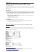
U140A135-00 1 QUICK START: DS Series, DS-RPC Series by Bay Technical Associates The DS-Series or DS-RPC Series is a console control data switch for applications that require control of multiple peripherals from a single host such as remote site management, out-of-band management, general data switching, etc. Installation The DS Series or DS-RPC Series base units come with optional input modules such as the DS 71, DS71MD3, DS62, DS72, DS73 and DS74.
U140A135-00 Unit Configuration 2 At the prompt, type the number associated with the module you want to access, followed by a . You will be taken to the module’s configuration window where you will be able to edit any of the information as shown in Figure 3. The following pages define each line of the configuration menu. Figure 3 Status Used to view the status of the installed modules, modem setup, login setup, assigned user ports and associated information by issuing a series of carriage returns.
U140A135-00 Port Select Code 3 The Port Select Code is an ASCII character string sent by the host terminal to the module to select an I/O port on a DS74 peripheral module. The Port Select Code’s factory default setting is $BT and is programmable up to 8 characters as shown in Figure 6. Figure 6 Attention Character Attention Character = semi-colon (;). Pressing the attention character 5 consecutive times will return back to the main menu.
U140A135-00 4 Header This allows the user to have limited control over the Header, either enable or disable option to display the Header upon connection to the host module. NOTE: The header may appear different depending on the type of module installed. Access Control This will allow you to access the menu where you can modify such options as prompting for usernames and passwords for both network and serial port access. Menu This allows user to enable or disable the Menu on start up.
U140A135-00 5 Figure 12 Unit ID The unit ID (64 char. Max) appears in the DS series module Main Menu and uniquely identifies the unit as shown in Figure 13. Figure 13 For more detailed information on the DS71 modules, follow this link: http://www.baytech.net/ftp_series.shtml#manuals, then look under DS Series.
U140A135-00 6 DS62 - Ethernet & RS232 host module for DS SERIES chassis Operation Once connected you will see the menu screen as shown in Figure 14. This shows the operation of the unit. Depending on which Network host module you have, the below screens may vary. The screens below are show with the DS62 module. When prompted at the unit’s startup menu select “C” followed by a . This will take you to the Configuration menu.
U140A135-00 Serial Port Configuration 7 The DS-Series host modules can use different serial port configurations as shown in Figure 16. Handshaking, Baud Rate, Word Size, Stop Bits, and Parity can all be configured through the serial port using the menus. RTS Line Driver, and DTR Line Driver cannot be configured using the serial port; they must be configured using the phone line. The default settings are 9600bps, 8 data bits, no parity, one stop bit, RTS and DTR low.
U140A135-00 Connect Port ID Echo 8 This identifies the module number and port number you are connected to. To change, select option 8, followed by a . To enable, select Y, followed by a as shown in Figure 20. The default setting is disabled. By selecting 2, followed by a , you can echo the module and port number. By selecting 3, followed by a , you can echo the device name.
U140A135-00 9 Figure 22 IP Address The IP address is the network address assigned by your network manager for your network. The IP address consists of four bytes, each byte ranging from 0 to 255. NOTE: There should be no active connections while configuring the DS62 module.
U140A135-00 10 SSH Enable/Disable Secure Shell (SSH), sometimes known as Secure Socket Shell, is a Unix-based command interface and protocol for securely getting access to a remote computer. It is widely used by network administrators to control Web and other kinds of servers remotely. Default setting is enabled. SSH Host Key Generation Selecting this option will allow the user to generate a SSH host key. A SSH host key is used as part of SSH encryption process.
U140A135-00 11 Figure 24 RPC Management Allow you to set all variables of the RPC unit remotely without ever entering the firmware of the RPC itself as shown in Figure 25. Figure 25 Web Server Configuration You can Enable or Disable Web Server capabilities in this menu. Such capabilities include: Web Login, Web Secure Login, and Web Login Activity Timeout as shown in Figure 26.
U140A135-00 12 DS72 - Ethernet & RS232 host module for DS SERIES chassis Operation Once connected you will see the menu screen as shown in Figure 27. Depending on which Network host module you have, the below screens may vary. The screens below are show with the DS72 module. When prompted at the unit’s startup menu select “C” followed by a . This will take you to the Configuration menu. Figure 27 Configuration The configuration menu allows the user to choose which unit they would like to access.
U140A135-00 Status 13 Used to view the status of the installed modules, network setup, login setup, and associated information by issuing a series of carriage returns. Serial Port Configuration The DS-Series host modules can use different serial port configurations as shown in Figure 30. The Baud Rate, Word Size, Stop Bits, and Parity can all be configured through the serial port using the menus.
U140A135-00 14 treats the character as data, not an attention character; thereby preventing unwanted port disconnection. The Timeguard session will disconnect your session if you have been idle too long. The default setting is disabled as shown in Figure 34. Figure 34 Connection Override This feature allows the user to override another user’s connection and force priority over other users. The default setting is enabled as shown in Figure 35.
U140A135-00 15 Manage Users This will allow access to the menu that allows the administrator to change user passwords or add new users. Up to 19 users plus an administrator allowed. Usernames are case sensitive and alphanumeric. Password This will allow the admin to access the menu to set up or change passwords for either network or serial port access. Menu This allows the admin or user to enable or disable this option to show the Menu on start up.
U140A135-00 16 Carriage Return Translation This option enables the DS72 Telnet processor to strip line feeds or nulls, which follow carriage returns. Default setting is disabled. Break Length Users may configure the DS72 for a break length of 1 to 1000 milliseconds. When a user, running a Telnet session with the DS72 and connected to a serial port on a DS74, sends a Telnet break command (0xF3) to the DS72, the serial port will send a break signal of the programmed duration.
U140A135-00 17 Figure 42 RPC Management If your DS72 module has this option, this allows you to set the temperature, voltage and current threshold alarms for the unit remotely without ever entering the firmware of the RPC itself as shown in Figure 43. Figure 43 Configure Another Module This option enables you to view the menu where the installed modules are listed as shown in Figure 44. Figure 44 For more detailed information on the DS72 modules, follow this link: http://www.baytech.net/ftp_series.
U140A135-00 18 DS73 or DS73TP - Ethernet peripheral module for DS SERIES chassis Operation Once connected you will see the menu screen as shown in Figure 45. This shows the operation of the unit. When prompted at the unit’s startup menu select “C” followed by a . This will bring you to the Configuration menu as shown in Figure 46. Figure 45 Figure 46 Configuration At the prompt, type the number associated with the module you want to access, followed by a .
U140A135-00 Figure 48 For more detailed information on the DS73 modules, follow this link: http://www.baytech.net/ftp_series.shtml#manuals, then look under DS Series.
U140A135-00 20 DS74 Operation Once connected you will see the menu screen as shown in Figure 49. This shows the operation of the unit. When prompted at the unit’s startup menu select “C” followed by a . This will bring you to the Configuration menu as shown in Figure 50. Figure 49 Figure 50 Unit Configuration At the prompt, type the number associated with the module you want to access, followed by a .
U140A135-00 Serial Port Configuration 21 DS-Series host modules translate data for devices using different serial configurations as shown in Figure 53. The Baud Rate, Word Size, Stop Bits, and Parity can all be configured through the serial port using the self-explaining menus. Select the parameter to change, make the change, and then save to non-volatile memory. Xon/Xoff, RTS Line Driver, and DTR Line Driver cannot be configured using the serial port; they must be configured using the phone line.
U140A135-00 22 DS-RPC – RPC Controller for DS-RPC SERIES chassis RPC Unit If you are using a DS-RPC unit, access to the RPC portion of the unit can be reached by selecting the number that corresponds with the RPC unit number as shown in Figure 55. NOTE: At any time during the session you need to go to the main menu or device menu, use the Attention Character = semi-colon (;). By pressing the attention character key 5 consecutive times, will return back to the main status menu.
U140A135-00 23 RPC Configuration: Type config followed by a . This screen will enable you to edit any of the information listed on the following pages as shown in Figure 57. Figure 57 Manage Users: The Manage Users menu shown in Figure 58 allows the admin to add, delete, or rename usernames. This menu also allows the administrator to edit the level of outlet access the user is granted. Figure 58 User Access: Once you add a user, you can grant/restrict the outlets assigned to a user.
U140A135-00 24 Figure 59 Help Menu: At the Status Menu shown in Figure 60, type Help followed by a to view the line commands for the DS-RPC’s. Figure 60 For more detailed information on the DS-RPC units, follow this link: http://www.baytech.net/ftp_series.shtml#manuals, then look under DS-RPC Series.
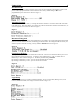
U140A135-00 25 Cables and Adapters RS-232 Port (DS) RS-232 Port (RPC) COM Port DE-9 Pin COM Port DB-25 Pin DTR 1 1 4 20 DSR GND 2 2 1 GND RTS 3 3 7 5 CTS TxD 4 4 3 2 RxD RxD 5 5 2 3 TxD DSR 6 N/C 6 6 DTR GND 7 7 5 7 GND CTS 8 8 4 RTS Signal DTR 4 DCD RI 8 1 9 DCD 8 DTR 22 Listed are the pin specifications for the BayTech cable and adapters and the terminal COM ports: 9FRJPC-4 RJ08X007