Hull Identification Number: _____________________________________________ Engine Serial Number: _________________________________________________ The Hull Identification Number (HIN) is located on the starboard side of the transom. Be sure to record the HIN in the space provided above and always refer to the HIN for all correspondence or orders. TYPICAL HIN LOCATION STARBOARD TRANSOM BOARDING LADDER © 2001 Bayliner Technical Publications. All rights reserved.
CONTENTS CHAPTER 1: ABOUT THIS MANUAL 1 1 2 2 3 3 4 5 Dealer Service Boating Experience Engine & Accessories Guidelines Qualified Maintenance Special Care For Moored Boats Safety Standards Hazard Warning Symbols Carbon Monoxide (CO) 5 6 6 Sources of CO Carbon Monoxide Alarm System What To Do If Carbon Monoxide Is Detected CHAPTER 2: PRODUCT SPECIFICATIONS 7 7 8 8 9 9 10 10 11 2150 (BX) 2150 (BZ) 2150 (CT) 2152 (BK) 2152 (CY) 2152 (BL) 2350 (BC) 2350 (BD) 2352 (BF) CHAPTER 3: COMPONENTS/SYSTEMS 12 13 14
18 19 20 Hull Exterior Drains & Hardware Quick Oil Drain System Fuel System 20 20 21 22 Bilge Blower Bilge Pump 22 24 25 25 26 27 Models, 2150BX and 2152BK Models, 2150CT and 2152CY Sleeper Seat Adjustment 29 29 30 31 Bilge Pump Testing Fresh Water System Marine Head With Pump-out Portable Toilet Alcohol Stove (2352BF Option) Jump Seat to Sunlounge Conversion 27 28 29 Fuel Fills and Vents Fuel Filters Operating Positions: Lounge positions: Canvas Top (Option) Installation Canvas Stowage CHAPTE
1 CHAPTER 1: ABOUT THIS MANUAL This Owner’s Manual Supplement provides specific information about your boat that is not covered in the Sport Boat Owner’s Manual. Study the Sport Boat Owner’s Manual and this supplement carefully. Pay particular attention to APPENDIX A: BAYLINER CAPRI LIMITED WARRANTY in this supplement. Keep the Sport Boat Owner’s Manual and this supplement on your boat in a secure, yet readily available place.
2 CHAPTER 1: ABOUT THIS MANUAL Engine & Accessories Guidelines Your boat’s engine and accessories were selected to provide optimum performance and service. Installing different engines or other accessories may cause unwanted handling traits. Should you choose to install a different engine or to add accessories that will affect the boat’s running trim, have an experienced marine technician perform a safety inspection and handling test before using your boat again.
CHAPTER 1: ABOUT THIS MANUAL 3 Special Care For Moored Boats If moored in saltwater or fresh water, your boat will collect marine growth on its hull bottom. This will detract from the boat’s beauty, greatly affect its performance and may damage the gelcoat. Periodically haul the boat out of the water and scrub the hull bottom with a bristle brush and a solution of soap and water.
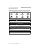
4 CHAPTER 1: ABOUT THIS MANUAL Hazard Warning Symbols The hazard warning symbols shown below are used throughout this supplement to call attention to potentially dangerous situations that could lead to either personal injury or product damage. Read these warnings and follow all safety instructions.
CHAPTER 1: ABOUT THIS MANUAL 5 Carbon Monoxide (CO) ! DANGER! CARBON MONOXIDE POISONING HAZARD! Carbon monoxide gas (CO) is colorless, odorless, and extremely dangerous. All engines, generators, and fuel burning appliances produce CO as exhaust. Direct and prolonged exposure to CO will cause BRAIN DAMAGE or DEATH. Signs of CO poisoning include headache, nausea, dizziness, and drowsiness. CO poisoning causes a significant number of boating deaths each year.
6 CHAPTER 1: ABOUT THIS MANUAL Factors increasing the effects of CO include: • Age. • Smokers or people exposed to high concentrations of cigarette smoke. • Consumption of alcohol. • Lung disorders, heart problems, and pregnancy. Carbon Monoxide Alarm System Your boat may feature a carbon monoxide (CO) alarm system. DO NOT DISCONNECT THE ALARM SYSTEM. Read and understand the manufacturer’s instructions for your CO alarm system.
7 CHAPTER 2: PRODUCT SPECIFICATIONS 2150 (BX) Overall Length Bridge Clearance Beam Maximum Draft Fuel Tank Capacity (gal) 20' 10'' 3' 11'' 8' 2'' 2' 11'' 40 Overall Length Bridge Clearance Beam Maximum Draft Fuel Tank Capacity (gal) 20' 10'' 3' 11' 8' 2'' 2' 11'' 40 2150 (BZ) Capri 21’ - 23’ • Owner’s Manual Supplement
8 CHAPTER 2: PRODUCT SPECIFICATIONS 2150 (CT) Overall Length Bridge Clearance Beam Maximum Draft Fuel Tank Capacity (gal) 20' 9'' 4' 3'' 8' 0'' 2' 11'' 37 Overall Length Bridge Clearance Beam Maximum Draft Fuel Tank Capacity (gal) 21' 3'' 4' 9'' 8' 2'' 2' 11'' 55 2152 (BK) Capri 21’ - 23’ • Owner’s Manual Supplement
CHAPTER 2: PRODUCT SPECIFICATIONS 9 2152 (CY) Overall Length Bridge Clearance Beam Maximum Draft Fuel Tank Capacity (gal) 20' 9'' 4' 6'' 8' 0'' 3' 0'' 37 2152 (BL) anchor locker Overall Length Bridge Clearance Beam Maximum Draft Fuel Tank Capacity (gal) 21' 3'' 4' 9'' 8' 2'' 2' 11'' 55 Capri 21’ - 23’ • Owner’s Manual Supplement
10 CHAPTER 2: PRODUCT SPECIFICATIONS 2350 (BC) Overall Length Bridge Clearance Beam Maximum Draft Fuel Tank Capacity (gal) 23' 10'' 5' 2'' 8' 4'' 3' 1'' 65 Overall Length Bridge Clearance Beam Maximum Draft Fuel Tank Capacity (gal) 23' 10'' 5' 2'' 8' 4'' 3' 1'' 65 2350 (BD) Capri 21’ - 23’ • Owner’s Manual Supplement
CHAPTER 2: PRODUCT SPECIFICATIONS 11 2352 (BF) Overall Length Bridge Clearance Beam 23' 10'' 5' 2'' 8' 4'' Maximum Fuel Tank Draft Capacity (gal) 3' 1'' 65 Optional Water Tank Capacity (gal) 11 Capri 21’ - 23’ • Owner’s Manual Supplement
12 CHAPTER 3: COMPONENTS/SYSTEMS Electrical System (12Volt DC) Thoroughly read and understand this section, the electrical sections of the Sport Boat Owner’s Manual and all accessory manuals included in your boat’s owner’s packet. Wiring diagrams are provided in Chapter 4 of this supplement. ! • • • • • DANGER! EXTREME FIRE, ELECTRIC SHOCK and EXPLOSION HAZARD! To minimize the risks of fire, electric shock and explosion: NEVER install knife switches or other arcing devices in the fuel compartments.
CHAPTER 3: COMPONENTS/SYSTEMS 13 NOTICE Electrical connections are prone to corrosion. To reduce corrosion caused electrical problems, keep all electrical connections clean and apply a spray-on protectant that is designed to protect connections from corrosion. NOTICE VOLTAGES - All boats use either 110-volt AC/60 Hertz, 240-volt AC/60 Hertz or 220-volt AC/50 Hertz single phase systems, and 12-volt DC or 24volt DC. Electrical distribution panels are labeled with voltage and frequency of AC and DC.
14 CHAPTER 3: COMPONENTS/SYSTEMS Dash Programming (2150BX/BZ, 2152BK/BL only) M S Use the M “LCD Mode” switch to toggle through the 7 basic settings. Press both M “LCD Mode” and S “LCD Set” at the same time to enter or change values. Arrow(s) show current function. Clock M and S Depth, Ft/M M and S Distance Log Trip Log M and S To Reset to 0.0 Total Hours Trip Hours Seawater Temp (option) Capri 21’ - 23’ • Owner’s Manual Supplement M and S To Reset to 0.
CHAPTER 3: COMPONENTS/SYSTEMS S to set Hours M to go to Minutes S to set Minutes S decreases Depth Alarm Value-M to next 15 M to go to 24:12 S to Select M to exit S increases Depth Alarm Value-M to next S to Select Feet or Meters M to next S to Select Depth ON or OFF Note Setting Depth to METERS will change Distance and Trip logs to km (kilometers) and Seawater Temp (option) to C (centigrade) Note If you see ProG on the display you have entered the programing mode. Turn the key off to exit.
16 CHAPTER 3: COMPONENTS/SYSTEMS Controls Read and understand the Controls section of both the Sport Boat Owner’s Manual and engine manual, provided in the owner’s packet, for instructions and warranty information. Navigation and Interior Lights Read the navigation light section of the Sport Boat Owner’s Manual.
CHAPTER 3: COMPONENTS/SYSTEMS 17 Depth Finder Your boat may come equipped with a depth finder. It will provide you with measurements of water depth beneath the boat and in many cases it may help you locate schools of fish. The depth finder comes with its own manual. We suggest that you read it carefully before using the unit. ! WARNING! DO NOT use the depth finder as a navigational aid to prevent collision, grounding, boat damage or personal injury.
18 CHAPTER 3: COMPONENTS/SYSTEMS Hull Exterior Drains & Hardware BOW HATCH DRAIN TYPICAL BILGE PUMP DRAIN LOCATIONS COOLER DRAIN (ON PORT SIDE) SINK DRAIN ON SOME MODELS (OPTION) LIVE WELL DRAIN ON SOME MODELS (PORT SIDE) BOW EYE TYPICAL TRANSOM TRANSOM LADDER STERN EYE (TYPICAL) GARBOARD DRAIN Capri 21’ - 23’ • Owner’s Manual Supplement
CHAPTER 3: COMPONENTS/SYSTEMS 19 Quick Oil Drain System QUICK OIL DRAIN SYSTEM OIL DRAIN HOSE TRANSOM OIL DRAIN PLUG ENGINE OIL PAN GARBOARD DRAIN PLUG DRAW CORD BILGE GARBOARD DRAIN All stern drive models are equipped with a quick oil drain system. To drain the engine oil: 1. Remove the boat from the water. 2. Unscrew the garboard drain plug. 3. Pull the draw cord until the oil drain plug and the oil drain hose slide out of the garboard drain. 4.
20 CHAPTER 3: COMPONENTS/SYSTEMS Fuel System Fuel Fills and Vents Fuel fills are located either on the aft deck or on the side decks adjacent to the aft cockpit. Fuel receptacle caps are marked “GAS”. Fuel vents are normally located in the hull or transom below and in the same general area as the fill. If you have trouble filling the fuel tank, check to see that the fuel fill and vent lines are free of obstructions and kinks.
CHAPTER 3: COMPONENTS/SYSTEMS 21 Bilge Blower The bilge blower removes fumes from the engine compartment and draws fresh air into the compartment through the deck vents. To ensure fresh air circulation, use the bilge blower for at least four minutes before starting the engine, during starting, and while running the boat below cruising speed. TYPICAL BLOWER SYSTEM ! WARNING! FIRE/EXPLOSION HAZARD Operation of the blower system is NOT A GUARANTEE that explosive fumes have been removed.
22 CHAPTER 3: COMPONENTS/SYSTEMS Bilge Pump TYPICAL BILGE PUMP SYSTEM This boat is equipped with one electric, impeller type, bilge pump, located at the lowest point of the bilge. The flow rate of the pump is 8.3 gallons (31.6 liters) per minute. BILGE PUMP TRANSOM The bilge pump is controlled by a switch on the dash panel, which should turned on whenever water begins to accumulate in the bilge.
CHAPTER 3: COMPONENTS/SYSTEMS 23 If the bilge pump hose is not the problem, check the bilge pump housing for clogging debris as follows: To remove the power cartridge: TAB 1. Lift the tab while rotating the fins counter clockwise and lift out the power cartridge (Fig. 1). 2. Clear the housing of debris. FIN FIG. 1 To reinstall the power cartridge: 1. Make sure the “O” ring is properly located and coat the “O” ring with a light film of vegetable oil or mineral oil (Fig. 2). 2.
24 CHAPTER 3: COMPONENTS/SYSTEMS Fresh Water System Fresh water systems are available on some models. These pressure-type (demand) systems operate when the water pump switch (located near the sink in the cuddy cabin) is in the ON position. Turn the pump switch OFF when the boat is not in use and when the water tank is empty. Stored water can become stagnant and distasteful. Pump the water tank dry before leaving your boat unattended for long periods of time.
CHAPTER 3: COMPONENTS/SYSTEMS 25 Marine Head With Pump-out If your boat features a marine head and pump-out system, carefully read the manufacturer’s owner’s manual supplied in your owner’s packet. WASTE PUMP-OUT DECK FITTING WASTE TANK VENT FITTING WASTE TANK VENT HOSE PORT DASH PUMP-OUT HOSE MARIN E HEAD Portable Toilet PORTABLE TOILET STORAGE LOCATION (TYPICAL) Your boat may feature a portable toilet.
26 CHAPTER 3: COMPONENTS/SYSTEMS Alcohol Stove (2352BF Option) ! WARNING! Reduce the possibility of fire by removing all combustible materials away from the stove before/during use. If your boat features a single burner alcohol stove, carefully read and follow the manufacturer’s operating instructions supplied in your owner’s packet before using your stove for the first time. ! DANGER! CARBON MONOXIDE POISONING HAZARD! The alcohol stove is a potential source of dangerous carbon monoxide gas (CO).
CHAPTER 3: COMPONENTS/SYSTEMS 27 Jump Seat to Sunlounge Conversion Models, 2150BX and 2152BK ! DANGER! DANGER PERSONAL SAFETY HAZARD! DO NOT allow anyone to ride on the aft sunlounge cushions while underway or anytime the engine is running. Step - 1: Remove the jump seats (A) by unsnapping the safety straps (B) and lifting the seats up and pulling them forward. B A C E E A C MOTOR BOX D E B B Step - 2: Set the outboard edge of the jump seats on the cockpit ledges (C).
28 CHAPTER 3: COMPONENTS/SYSTEMS Models, 2150CT and 2152CY ! DANGER! DANGER PERSONAL SAFETY HAZARD! DO NOT allow anyone to ride on the aft sunlounge cushions while underway or anytime the engine is running. C A A C Step - 1: Remove the jump seats (A) by sliding them forward. MOTOR BOX A B Step - 2: Slide the lounge support inserts (B) into the lounge support slots (C). C Step - 3: Press down firmly on the inboard side of each jump seat until they rest firmly on the motorbox ledges.
CHAPTER 3: COMPONENTS/SYSTEMS 29 Sleeper Seat Adjustment Your boat may be equipped with adjustable sleeper seats. These seats can be adjusted fore and aft in the upright position. The seat bottoms of these models also adjust into backrests while the seat is in the lounge position. Operating Positions: To slide seat forward: OPERATING POSITIONS 1. Lift forward seat at point (A). 2. Push down on forward seat at point (B) and pull seat forward. SEAT BOTTOM 3.
30 CHAPTER 3: COMPONENTS/SYSTEMS Canvas Top (Option) Installation CANVAS INSTALLATION (TYPICAL VIEW) G L F H E I K J M B D A C 1. Insert eye ends (A) of main bow (B) into deck hinges (C) and secure with pins (D). 2. Unfold canvas top and snap front edge of top (E) to windshield frame. 3. Close front zipper (F). 4. Pull aft on aft edge of top (G), making sure canvas lies evenly from side to side, and hook hold down straps (H) to deck loops (I). 5.
CHAPTER 3: COMPONENTS/SYSTEMS ! 31 CAUTION! Take down and securely stow the convertible top, side curtains and back cover before transporting your boat by road. Canvas Stowage Your boat may feature ventilated stowage space for the canvas top under either the canvas stowage cover or the aft sunlounge pad.
32 CHAPTER 4: WIRING DIAGRAMS 2150BX, 2150BZ, 2150BK and 2152BL Capri 21’ - 23’ • Owner’s Manual Supplement
CHAPTER 4: WIRING DIAGRAMS 33 2150CT, 2152CY, 2350BC, 2350BD and 2350BF Capri 21’ - 23’ • Owner’s Manual Supplement
34 APPENDIX A: BAYLINER CAPRI LIMITED WARRANTY Bayliner provides the following BAYLINER CAPRI LIMITED WARRANTY to the original retail purchasers of its 2002/2003 Capri model boats, purchased from an authorized dealer, operated under normal, noncommercial use: Limited Lifetime Structural Hull Warranty The selling dealer will repair or replace, at Bayliner’s option, any Structural Hull Failure, as defined below, which is caused by a defect in factory materials or workmanship, for as long as the original pur
Owner’s Notes
Owner’s Notes
B a y lin e r M a r in e • P. O.