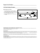
Engine Serial Number: _____________________________________________ Hull Identification Number:__________________________________________ Hull Identification Number • The Hull Identification Number (HIN) is located on the starboard side of the transom. • Record the HIN (and the engine serial numbers) in the space provided above. • Include the HIN with any correspondence or orders. HIN LOCATION TRANSOM © 2003 Bayliner Technical Publications. All rights reserved.
CONTENTS 1 Chapter 1: Welcome Aboard! 10 Chapter 2: Features / Systems 1 Dimensions and Tank Capacities 10 Hull Hardware 1 Layout View 11 Deck Hardware 11 Anchor Windlass (If Equipped) 1 Dealer Service 1 Warranty Information 12 Helm 2 Boating Experience 13 Electrical System 2 Safety Standards 14 3 Engine & Accessory Guidelines 3 Engine & Accessory Literature 3 Qualified Maintenance 3 Structural Limitations 4 Special Care For Moored Boats 4 5 6 17 Sling Placement Carbon
22 Appliances 34 22 Alcohol or Alcohol/Electric Stove (If Equipped) 22 Microwave Oven (If Equipped) 22 Refrigerator (If Equipped) 23 23 35 Portable Toilet (If Equipped) 23 Engine 35 Air Conditioning System (If Equipped) Fuel System 37 Canvas Top (If Equipped) 38 Chapter 3: Electrical Routings 24 Engine Room Ventilation System 25 Quick Oil Drain System 38 Bilge Pumps Hull Harnesses Routings 38 39 40 41 Controls 26 Power Trim and Tilt 26 Trim Tabs 27 34 Using The Marine Head 34 Winteri
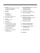
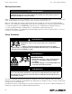
Hazard Boxes & Symbols The hazard boxes and symbols shown below are used throughout this Supplement to call attention to potentially dangerous situations which could lead to either personal injury or product damage. Read ALL warnings carefully and follow all safety instructions. ! DANGER! This box alerts you to immediate hazards which WILL cause severe personal injury or death if the warning is ignored.
265 • Owner’s Manual Supplement Chapter 1: Welcome Aboard! This Owner’s Manual Supplement provides specific information about your boat that is not covered in the Cruiser & Yacht Owner’s Manual. Please study the Cruiser & Yacht Owner’s Manual and this Supplement carefully. Keep the Cruiser & Yacht Owner’s Manual and this Supplement on your boat in a secure, yet readily available place.
Chapter 1: Welcome Aboard! 265 • Owner’s Manual Supplement Boating Experience ! WARNING! CONTROL HAZARD! A qualified operator must be in control of the boat at all times. DO NOT operate your boat while under the influence of alcohol or drugs. If this is your first boat or if you are changing to a type of boat you are not familiar with, for your own comfort and safety, obtain handling and operating experience before assuming command of the boat. Take one of the boating safety classes offered by the U.S.
265 • Owner’s Manual Supplement Chapter 1: Welcome Aboard! Engine & Accessory Guidelines NOTICE When storing your boat please refer to your engine’s operation and maintenance manuals. • Your boat’s engines and accessories were selected to provide optimum performance and service. • Installing different engines or other accessories may cause unwanted handling characteristics.
Chapter 1: Welcome Aboard! 265 • Owner’s Manual Supplement Special Care For Moored Boats NOTICE • To help seal the hull bottom and reduce the possibility of gelcoat blistering on moored boats, apply an epoxy barrier coating. The barrier coating should be covered with several coats of anti-fouling paint. • Many states regulate the chemical content of bottom paints in order to meet environmental standards.
265 • Owner’s Manual Supplement Chapter 1: Welcome Aboard! Boat Lifting ! WARNING! PERSONAL INJURY and /or PRODUCT OR PROPERTY DAMAGE HAZARD! • Lifting slings may slip on the hull. Avoid serious injury or death by securing the slings together before lifting. ! CAUTION! PRODUCT OR PROPERTY DAMAGE HAZARD! • When lifting any boat, always use a spreader bar. The spreader bar must be equal to the width of the boat at the lifting point. • Always follow the lift equipment’s instructions and requirements.
Chapter 1: Welcome Aboard! 265 • Owner’s Manual Supplement Carbon Monoxide (CO) ! DANGER! • Carbon monoxide gas (CO) is colorless, odorless, tasteless, and extremely dangerous. • All engines, generators, and fuel burning appliances produce CO as exhaust. • Prolonged exposure to low concentrations or very quick exposure to high concentrations will cause BRAIN DAMAGE or DEATH. • Teak surfing, dragging, or water skiing within 20 feet of a moving watercraft can be fatal.
265 • Owner’s Manual Supplement Chapter 1: Welcome Aboard! Where and How CO Can Accumulate Stationary Conditions That Increase CO Accumulations Include: A. Using engine, generator, or other fuel burning device when boat is moored in a confined space. B. Mooring too close to another boat that is using its engine, generator, or other fuel burning device. To correct stationary situations A and/or B: • Close all windows, portlights and hatches. • If possible, move your boat away from source of CO.
Chapter 1: Welcome Aboard! 265 • Owner’s Manual Supplement Trip Checklist ❏ Make sure you know where the exhaust outlets are located on your boat. ❏ Educate all passengers about the symptoms of CO poisoning and where CO may accumulate. ❏ When docked, or rafted with another boat, be aware of exhaust emissions from the other boat. ❏ Confirm that water flows from the exhaust outlet when the engines and generator are started.
265 • Owner’s Manual Supplement Chapter 1: Welcome Aboard! More Information For more information about how you can prevent carbon monoxide poisoning on recreational boats and other ways to boat more safely, contact: United States Coast Guard Office of Boating Safety (G-OPB-3) 2100 Second Street SW Washington, DC 20593 www.uscgboating.org 1-800-368-5647 National Marine Manufacturers Association (NMMA) 200 East Randolph Drive Suite 5100 Chicago, IL 60601-9301 www.nmma.
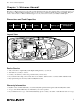
265 • Owner’s Manual Supplement Chapter 2: Features / Systems Hull Hardware FUEL AND AFT BILGE WASTE TANK VENTS PUMP STORAGE DRAIN STARBOARD HULLSIDE BOW EYE COCKPIT DRAINS FWD BILGE PUMP SHOWER SUMP HEAD SINK WATER TANK VENT PORT HULLSIDE ANCHOR LOCKER DRAIN AIR CONDITIONING OVERBOARD (IF EQUIPPED) AIR CONDITIONING DRAIN (IF EQUIPPED) COCKPIT DRAINS GALLEY DRAIN TRANSOM TRIM TAB (TYPICAL) 10 STERN EYES GARBOARD MACERATOR DRAIN DISCHARGE (IF EQUIPPED) RETRACTABLE BOARDING LADDER
265 • Owner’s Manual Supplement Chapter 2: Features / Systems Deck Hardware FORWARD DECK HARDWARE AFT DECK HARDWARE AFT FWD NAVIGATION BOW LIGHT (TYPICAL) CLEAT ANCHOR ROLLER WATER FILL ROPE CHOCK (TYPICAL) GRAB HANDLES WASTE DECK FUEL PUMP-OUT CLEAT FILL FITTING (TYPICAL) Anchor Windlass (If Equipped) Your boat may feature an anchor windlass. Read the manufacturer’s instruction manual supplied in your boat’s owner’s packet before using the anchor windlass for the first time.
Chapter 2: Features / Systems 265 • Owner’s Manual Supplement Helm WINDLASS CONTROLS (IF EQUIPPED) INSTRUMENT PANEL 12 VOLT ACCESSORY OUTLET TILT STEERING (IF EQUIPPED) SWITCH PANEL CIRCUIT BREAKERS INSTRUMENT PANEL VOLTMETER FUEL GAUGE SPEEDOMETER TRIM TAB GAUGE HORN SWITCH BLOWER SWITCH 12 FWD & AFT BILGE PUMP SWITCHES IGNITION ACCESSORY SWITCHES TEMPERATURE GAUGE DEPTH FINDER (IF EQUIPPED) ACCESSORY SWITCH PANEL COCKPIT LIGHTS OIL PRESSURE GAUGE ANCHOR LIGHTS TACHOMETER NAVIGATI
265 • Owner’s Manual Supplement Chapter 2: Features / Systems Electrical System Thoroughly read and understand this section and the electrical sections of the Cruiser & Yacht Owner’s Manual and all accessory manuals included in your boat owner’s packet. Electrical routing drawings are provided in Chapter 3 of this supplement, wiring schematics in Chapter 4.
Chapter 2: Features / Systems 265 • Owner’s Manual Supplement 12 Volt DC System Fuses and Circuit Breakers DC MAIN FORWARD BILGE PUMP MAIN CIRCUIT BREAKER PANEL AFT BILGE PUMP ACCESSORY • The 12 volt DC electrical system is protected by a large circuit breaker located on the engine. • The accessories are protected by circuit breakers on the battery switch panel and by circuit breakers on the main circuit breaker panel.
265 • Owner’s Manual Supplement Chapter 2: Features / Systems Batteries The batteries supply electricity for lights, accessories and engine starting. The electrical section of Chapter 8, in the Cruiser & Yacht Owner’s Manual, provides battery care and maintenance instructions. Battery Charger (If Equipped) ! CAUTION! The battery charging systems (alternator and battery charger) installed on your boat are designed to charge conventional lead-acid batteries.
Chapter 2: Features / Systems 265 • Owner’s Manual Supplement Battery Switch NOTICE Since the batteries on your boat were dealer-installed, the battery switch positions listed above may vary. Make sure you get a full explanation of battery switch use from your selling dealer.
265 • Owner’s Manual Supplement Chapter 2: Features / Systems Shore Power- 120V/60Hz AC System (If Equipped) ! DANGER! • • • • • FIRE, EXPLOSION & SHOCK HAZARD! DO NOT alter shore power connectors and use only compatible connectors. Before connecting or disconnecting the shore power cord to your boat, make sure all breakers and switches on the AC master panel are turned Off.
Chapter 2: Features / Systems 265 • Owner’s Manual Supplement Water Heater ! CAUTION! WATER HEATER DAMAGE HAZARD! DO NOT energize the water heater electrical circuit until the heater is COMPLETELY filled with water. The tank is full if water flows from the tap when the hot water is turned On in the galley. Even momentary operation in a dry tank will damage the heating elements. Warranty replacements WILL NOT be made on elements or tank damaged in this manner.
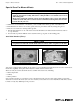
265 • Owner’s Manual Supplement Chapter 2: Features / Systems Connecting To Shore Power TYPICAL SHORE POWER INLETS DUAL INLET (IF EQUIPPED) SHORE POWER INLETS PORT SIDE OF DECK DUAL SHORE POWER AC PANEL (IF EQUIPPED) LINE 1 DOCKSIDE MASTER VOLTMETER SELECTOR SWITCH VOLTMETER LINE 1 POLARITY LIGHT LINE 2 TRANSFER LINE 2 DOCKSIDE MASTER LINE 2 POLARITY LIGHT 10 AMPS 15 AMPS 20 AMPS 15 AMPS 5 AMPS 15 AMPS 25 AMPS 15 AMPS FIGURE 1 1. 2. 3. • • 4. 5. 6.
Chapter 2: Features / Systems 265 • Owner’s Manual Supplement Line 2 Transfer switch (Dual Shore Power Only) NOTICE • When using the "Line 2 Transfer Switch" do not exceed 30 total amps. • The amperage of each component breaker is shown in figure 1, on the previous page. • The voltage on each line can be read by setting the voltmeter selector switch. When only one dockside outlet is available, you can use the "Line 2 Transfer Switch" to provide power to both lines. 1.
265 • Owner’s Manual Supplement Chapter 2: Features / Systems Navigation & Communication Equipment The owner’s packet contains manuals for all navigation & communication equipment installed on your boat. Thoroughly read and understand these manuals before using these systems. Also, read the warnings below carefully and follow all safety instructions. VHF Radio (If Equipped) Your boat may include a VHF (Very High Frequency) radio at the helm.
Chapter 2: Features / Systems 265 • Owner’s Manual Supplement Appliances NOTICE Always keep an approved ABC-type fire extinguisher in galley area. All appliances installed on your boat come with their own manuals that contain detailed instructions and important safeguards. Thoroughly read and understand these manuals before using your boat’s appliances. • Make sure the AC breaker is turned On for the appliance you wish to use.
265 • Owner’s Manual Supplement Chapter 2: Features / Systems Propulsion Engine The owner’s packet contains detailed engine operation and maintenance manuals. Be sure to read and understand these manuals before operating or performing maintenance to the engine. Fuel System ! WARNING! FIRE/EXPLOSION HAZARD It is very important that the fuel system be inspected thoroughly the first time it is filled and at each subsequent filling.
Chapter 2: Features / Systems 265 • Owner’s Manual Supplement Fuel Filters • The fuel pickup tube (located inside the fuel tank) is equipped with a fine mesh screen filter. • In addition, when supplied by the engine manufacturer, a fuel filter is installed on the engine. • Periodically replace the fuel filters to make sure they remain clean and free of debris. • Consult with your selling dealer or local marina concerning fuel additives that help to prevent fungus or other buildup in your fuel tank.
265 • Owner’s Manual Supplement Chapter 2: Features / Systems Quick Oil Drain System QUICK OIL DRAIN SYSTEM TRANSOM OIL DRAIN HOSE OIL DRAIN PLUG ENGINE OIL PAN GARBOARD DRAIN PLUG DRAW CORD BILGE GARBOARD DRAIN To drain the engine oil: 1. 2. 3. 4. 5. 6. 7. 8. Remove the boat from the water. Unscrew the garboard drain plug. Pull the draw cord until the oil drain plug and the oil drain hose slide out of the garboard drain. Place the end of the oil drain hose into a suitable container.
Chapter 2: Features / Systems 265 • Owner’s Manual Supplement Controls Power Trim and Tilt The stern drive on your boat is equipped with power trim and tilt. Trim and tilt instructions are provided in the engine operation manual and the shifter/ throttle manual, included in your owner’s packet.
265 • Owner’s Manual Supplement Chapter 2: Features / Systems Bilge Pumps NOTICE Discharge of oil, oil waste or fuel into navigable waters is prohibited by law. Violators are subject to legal action by the local authorities. • Your boat is equipped with two impeller-type bilge pumps. • The bilge pumps are automatically controlled by float switches (see "Autofloat Switches" on the next page). • The bilge pumps can also be controlled by switches on the dash.
Chapter 2: Features / Systems 265 • Owner’s Manual Supplement Autofloat Switches • Automatic bilge pumps use electromagnetic float (autofloat) switches to turn On the pump whenever water rises above a preset level in the bilge. • One autofloat switch is mounted next to each automatic bilge pump. • Autofloat switches are wired directly to the battery and will normally function even when the boat is completely shut down and left unattended.
265 • Owner’s Manual Supplement Chapter 2: Features / Systems Freshwater Systems (If Equipped) WATERLINE ROUTING WATERLINE ROUTING (IF EQUIPPED) WATERLINE TO GALLEY WATERLINE TO HEAD WATER TANK WATER FILTER TO GALLEY WATER FILL FITTING TO HEAD AFT PORT DECK AFT WATER TANK TRANSOM SHOWER WATER FILTER WATER PUMP GALLEY FAUCET HOT WATER LINE PORT TRANSOM WATER PUMP SWITCH COLD WATER LINE WATER PUMP WATER HEATER Your boat may feature a pressure-demand freshwater (potable) system.
Chapter 2: Features / Systems 265 • Owner’s Manual Supplement Freshwater System Winterization ! CAUTION! WATER SYSTEM DAMAGE HAZARD! Never blow compressed air through the water system when all of the faucets are Closed. 1. Turn On the water system switch. 2. Open all of the faucets and showers and let the water system drain completely. 3. Turn Off the water system switch. Any remaining water must be removed from the water lines.
265 • Owner’s Manual Supplement Chapter 2: Features / Systems Water Heater (If Equipped) ! WARNING! HOT HAZARD! Water heated by the water heater will reach temperatures high enough to scald the skin. ! CAUTION! WATER HEATER DAMAGE HAZARDS! • DO NOT energize the AC water heater electrical circuit until the heater is completely filled with water. Even momentary operation in a dry tank will damage the heating elements. Warranty replacements will not be made on elements or tank damaged in this manner.
Chapter 2: Features / Systems 265 • Owner’s Manual Supplement Sink and Shower Drains SHOWER DRAIN SYSTEM Gray water (water from sinks and showers) above the waterline is gravity drained overboard, while gray water below the waterline is pumped overboard. TO THRU HULL Shower Drain System Water from the head shower is pumped overboard. • The shower drain pump is controlled by a switch near the sink. • Turn the shower drain pump On whenever the shower is used.
265 • Owner’s Manual Supplement Chapter 2: Features / Systems Seawater Systems (If Equipped) Seacocks A seacock is a valve, controlled by a 90º lever, used to manage the pickup of seawater through the hull and below the water line. Seacocks are typically used on your boat in the following seawater pickup systems: • Marine head (toilet) • Air conditioning system Before using any of these systems, make sure that the system’s seacock is Open and remains Open until the system is shut Off.
Chapter 2: Features / Systems 265 • Owner’s Manual Supplement Marine Head With Holding Tank (If Equipped) MARINE HEAD SYSTEM FT HEAD PICKUP LOCATED BELOW ENTRY STEP A Your boat may be equipped with a marine head (toilet) and waste holding tank system. Be sure to read the manufacturer’s manual (included in your boat’s owner’s packet). • The marine head installed on your boat uses seawater to flush waste from the toilet. The seawater pickup valve (seacock) is located under the entry steps in the cabin.
265 • Owner’s Manual Supplement Chapter 2: Features / Systems Macerator (If Equipped) NOTICE Check with local authorities for regulations regarding the legal use of marine head systems. MACERATOR SYSTEM (IF EQUIPPED) MACERATOR WASTE PUMP OUT DECK FITTING UNDERWATER DISCHARGE SEACOCK MACERATOR SWITCHES To use the macerator to pump waste directly into the water (where regulations permit): 1. Open the underwater discharge seacock located in the engine compartment on the starboard transom. 2.
Chapter 2: Features / Systems 265 • Owner’s Manual Supplement HOSE TO AIR COND UNIT SEAWATER PUMP AIR CONDITIONER UNIT LOCATED IN V-BERTH BUNK AIR COND OVERBOARD AIR COND UNIT SEAWATER STRAINER AFT AIR COND DRAIN SEAWATER PICK-UP AIR COND SUMP PUMP PORT ENGINE COMPARTMENT STBD AFT AIR COND VENT AIR CONDITIONER DUCT ROUTING GALLEY AIR COND VENT CONNECTS TO AIR COND UNIT AIR COND VENT AIR COND SWITCH PANEL AIR COND VENT ON AFT SIDE OF GALLEY Your boat may be equipped with an air conditioning
265 • Owner’s Manual Supplement Chapter 2: Features / Systems Canvas Top (If Equipped) ! CAUTION! Take down and securely stow the convertible top, side curtains and back cover before transporting your boat by road. B E C F I A H G DET AIL W VIE IL TA DE VIE W D 1. Slide the swivel ends (A) of the main bow (B) over the side windshield frames (C) and insert the pins (D). 2. Unfold the canvas top and slide the swivel ends of the forward legs (E) over the windshield frame and insert the pins. 3.
265 • Owner’s Manual Supplement Chapter 3: Electrical Routings Hull Harnesses Routings AC Hull Harness Routings (If Equipped) AC PANEL ELECTRIC STOVE FORWARD AC HARNESS ROUTING MICROWAVE GALLEY OUTLET AIR CONDITIONER (IF EQUIPPED) FWD HEAD OUTLET REFRIGERATOR OUTLET (IF EQUIPPED) AFT AC HARNESS ROUTING WATER HEATER FORWARD TO AC PANEL BATTERY CHARGER AFT TO DASH AIR CONDITIONER PUMP (IF EQUIPPED) 38
265 • Owner’s Manual Supplement Chapter 3: Electrical Routings DC Hull Harness Routings FORWARD DC HARNESS 12 VOLT ACCESSORY STEP LIGHT WATER PUMP SWITCH STEREO FWD FORWARD BILGE PUMP SHOWER DRAIN PUMP TO HEAD REFRIGERATOR (IF EQUIPPED) TO DASH AFT DC WIRE ROUTING TRIM TAB PUMP WATER PUMP TO GALLEY BATTERY CHARGER (IF EQUIPPED) ENGINE GROUND AFT ENGINE PLUG BONDING BLOCK MACERATOR (IF EQUIPPED) GROUNDING BUSS BAR BLOWER TRIM/TILT AFT BILGE PUMP FUEL TANK TO BATTERY SWITCH TO DASH
Chapter 3: Electrical Routings 265 • Owner’s Manual Supplement Battery Cable Routings POSITIVE BATTERY CABLE ROUTINGS PORT BATTERY TO WINDLASS (IF EQUIPPED) AFT ENGINE STARTER TRIM/TILT PUMP STARBOARD BATTERY TO BATTERY SWITCH TO DASH NEGATIVE BATTERY CABLE ROUTINGS PORT BATTERY TO WINDLASS (IF EQUIPPED) ENGINE GROUND AFT ENGINE STARTER TRIM/TILT PUMP 40 STARBOARD BATTERY
265 • Owner’s Manual Supplement Chapter 3: Electrical Routings Bonding Harness Routing FUEL TANK HEAD PICKUP AIR CONDITIONER (IF EQUIPPED) AFT BONDING BLOCK MACERATOR THRU-HULL (IF EQUIPPED) GROUNDING BUSS BAR AIR CONDITIONER PICKUP (IF EQUIPPED) AIR CONDITIONER STRAINER (IF EQUIPPED) AIR CONDITIONER PUMP (IF EQUIPPED) 41
Chapter 3: Electrical Routings 265 • Owner’s Manual Supplement Deck Harness Routings NOTE: VIEW IS OF UNDERSIDE OF DECK HORN SPEAKER NAVIGATION LIGHT WINDLASS (IF EQUIPPED) V-BERTH LIGHTS DINETTE LIGHTS WIPER GALLEY LIGHTS HEAD LIGHTS ENTRY LIGHTS COMPASS (IF EQUIPPED) LIGHT SWITCH COURTESY LIGHTS AFT BERTH LIGHTS AFT BERTH LIGHT SPEAKER COURTESY LIGHT SPEAKER COURTESY LIGHT FUEL FILL GROUND TO GROUND BLOCK IN HULL 42 ALL AROUND LIGHT
265 • Owner’s Manual Supplement Chapter 4: Wiring Diagrams Direct Current Electrical System 43
Chapter 4: Wiring Diagrams AC Electrical System (If Equipped) Single Shore Power 44 265 • Owner’s Manual Supplement
265 • Owner’s Manual Supplement Chapter 4: Wiring Diagrams Dual Shore Power 45
265 • Owner’s Manual Supplement Important Records Selling Dealer Key Numbers Name Of Dealership Ignition Other Address Electronics Phone/FAX/E-mail Manufacturer Model Name/Number Sales Manager Serial Number Service Manager Manufacturer Model Name/Number Engine Serial Number Manufacturer Model Name/Number Engine Serial Number Oil Type/SAE Quarts per Engine Manufacturer Filter Type Propeller Model Name/Number Serial Number Manufacturer Model Name/Number Serial Number Manufacturer Pitc
265 • Owner’s Manual Supplement Float Plan Before going boating, fill out a copy of this float plan (or similar) and leave it with a reliable person whom you can depend on to contact the Coast Guard or other rescue organization, if you do not return as scheduled.
Float Plan 265 • Owner’s Manual Supplement Survival Equipment Trip Expectations Marine Radio (Yes/No) Type Frequencies Number of PFDs Flares (Yes/No) Mirror (yes or no) Smoke Signals (Yes/No) Flashlight (Yes/No) Food (Yes/No) Departing From Departure Date Departure Time Stopover 1 Water (Yes/No) Anchor (Yes/No) Raft/Dinghy (Yes/No) Arrive No Later Than: Date Paddles (Yes/No) EPIRB (Yes/No) Other Other Other Other Arrive No Later Than: Time Stopover 2 Arrive No Later Than: Date Ar
Owner’s Notes
Owner’s Notes
Owner’s Notes
Owner’s Notes
Part Number 1700660 Bayliner • P.O.