
Specifications


Chapter 2: Features / Systems 285 • Owner’s Manual Supplement
22
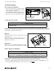
5. Switch the "Line 1 Dockside Master" On.
6. If equipped with dual dockside, switch the "Line 2 Dockside Master" On.
7. Turn On the individual component breakers as required.
Line 2 Transfer Switch (Dual Shore Power)
When only one dockside outlet is available, you can use the "Line 2 Transfer Switch" to provide power to both lines.
1. Connect to shore power as described in steps 1 through 4 above.
2. Switch the "Line 2 Transfer Switch" On instead of the "Line 2 Dockside Master".
3. Turn On the individual component breakers as required.
Lighting
Navigation and Interior Lights
Read and understand the navigation light section of the Cruiser & Yacht Owner’s Manual. The navigation and
interior lights installed on your boat are of top quality, but that they may occasionally fail for a variety of reasons:
1. There may be a blown fuse - replace the fuse.
2. The bulb may be burned out - carry spare bulbs for replacement.
3. A wire may be damaged or may have come loose - repair as required.
4. The bulb base may be corroded - clean the base and coat it with non-conductive electrical lubricant.
NOTICE
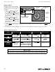
• When using the "Line 2 Transfer Switch" do not exceed 30 total amps.
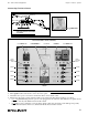
• The amperage of each component breaker is shown in figure 1, on the previous page.
• The voltage on each line can be read by setting the voltmeter selector switch.
• Avoid the storage of gear where it would block navigation lights from view.
• Be conservative in the use of battery power. Prolonged operation of cabin interior lights
(overnight) will result in a drained battery.
CAUTION!
!