
Specifications
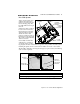
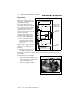
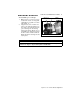
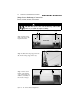
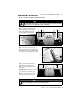
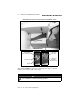
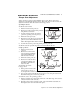
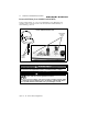
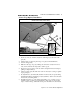

Table Of Contents
- ChapTER 1: ABOUT THIS MANUAL
- CHAPTER 2: PRODUCT SPECIFICATIONS
- ChapTER 3: COMPONENTS/sYSTEMS
- Electrical System (12Volt DC)
- Fuses and/or Circuit Breakers
- Dash Programming (1952BV only)
- Controls
- Navigation and Interior Lights
- Compass
- Depth Finder
- Bow Mount For Trolling Motor-1804PC and 1954CW
- Anchoring
- Ski Tow Ring
- Ski Pylon (outboard models)
- Hull Exterior Drains & Hardware
- Quick Oil Drain System
- Fuel System
- Bilge Blower
- Live Well System
- Bilge Pump
- Jump Seat to Sunlounge Conversion
- Sleeper Seat Adjustment
- Removable Fishing Seats (1804PC and 1954CW)
- Canvas Top (Option) Installation
- Canvas Stowage
- ChapTER 4: Wiring Diagrams
- Appendix A: BAYLINER CAPRI LIMITED WARRANTY
CHAPTER 3: COMPONENTS/SYSTEMS 25
Capri 16’ - 19’ • Owner’s Manual Supplement
Live Well System
Your boat may feature a live
well. The live well aerator
pump(s) are located aft, adja-
cent to the bilge pump. The
live well intakes are through-
transom.
Switches for the live well are
located on the forward elec-
trical panel and on the main
dash panel. These switches
activate the aerator that
pumps a continuous supply of
fresh water into the live well.
The overflow is automatically
drained overboard.
Occasionally check the live
well when it is operating to
see that the aerator is pump-
ing adequate amounts of water. If there appears to be a problem, check the system,
including the plastic screens over the transom intakes for weeds or other debris.
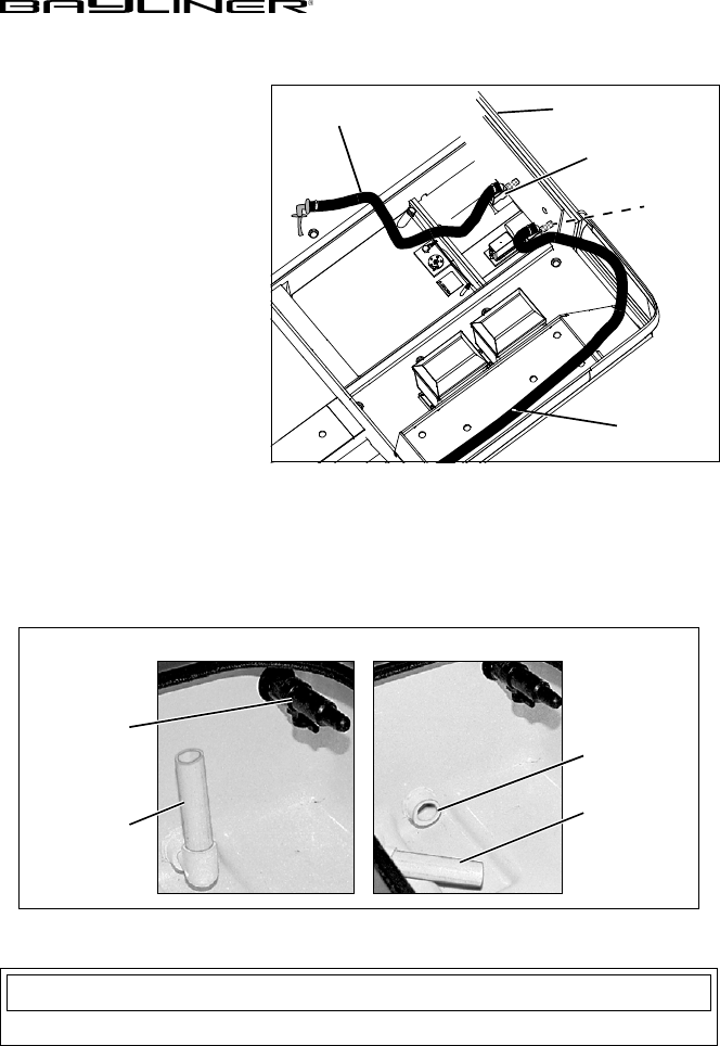
The livewell is drained by removing the stand pipe (see photos below) and allowing
water to drain completely.
TO FWD
TRANSOM
LIVE WELL
TO AFT
LIVE WELL
LIVE WELL
AERATOR PUMP
(TYPICAL)
PLASTIC
SCREEN
FILTER
STAND PIPE
LIVE WELL
STAND PIPE
ATTACHED
AERATOR
VALVE
REMOVED
DRAIN TO
THRU-HULL
The live well pump should be shut off while underway at planing speeds.
NOTICE