
Specifications
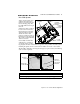
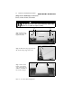
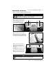
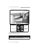
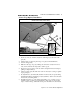

Table Of Contents
- ChapTER 1: ABOUT THIS MANUAL
- CHAPTER 2: PRODUCT SPECIFICATIONS
- ChapTER 3: COMPONENTS/sYSTEMS
- Electrical System (12Volt DC)
- Fuses and/or Circuit Breakers
- Dash Programming (1952BV only)
- Controls
- Navigation and Interior Lights
- Compass
- Depth Finder
- Bow Mount For Trolling Motor-1804PC and 1954CW
- Anchoring
- Ski Tow Ring
- Ski Pylon (outboard models)
- Hull Exterior Drains & Hardware
- Quick Oil Drain System
- Fuel System
- Bilge Blower
- Live Well System
- Bilge Pump
- Jump Seat to Sunlounge Conversion
- Sleeper Seat Adjustment
- Removable Fishing Seats (1804PC and 1954CW)
- Canvas Top (Option) Installation
- Canvas Stowage
- ChapTER 4: Wiring Diagrams
- Appendix A: BAYLINER CAPRI LIMITED WARRANTY

26 CHAPTER 3: COMPONENTS/SYSTEMS
Capri 16’ - 19’ • Owner’s Manual Supplement
Bilge Pump
This boat is equipped with one
bilge pump, located at the low-
est point of the bilge.
The electric bilge pump sup-
plied with your boat is an impel-
ler-type pump. It is controlled
by a switch on the dash panel,
which should be turned on
whenever water begins to accu-
mulate in the bilge.
Check the bilge pump often to
make sure it is working prop-
erly. To check the bilge pump:
• Turn on the dash-mounted
switch and make sure that
water in the bilge is pumped
overboard.
If bilge water is present and the
pump motor is running but not
pumping:
• Inspect the bilge pump hose
for a kink or collapsed area.
If the bilge pump hose is not the problem, check the bilge pump housing for clog-
ging debris:
To remove the power cartridge:
1. Lift the tab while rotating the fins
counter clockwise and lift out the
power cartridge (Fig. 1).
2. Clear the housing of debris.
TRANSOM
TYPICAL BILGE PUMP SYSTEM
BILGE
PUMP
THRU
HULL
TYPICAL PUMP
LOCATION IS
UNDER ENGINE
FIG. 1
TAB FIN