RTA04W ADSL2+ 11b/g HOME GATEWAY User Manual
CONTENT TABLE 1. INTRODUCTION ................................................................................................................. 4 2. APPLICATION .................................................................................................................... 4 3. TECHNICAL SPECIFICATIONS AND FEATURES .............................................................................. 5 4. PACKING LIST ......................................................................................
13.9. DMZ................................................................................................................................... 43 13.10. URL BLOCK ........................................................................................................................ 44 13.11. DOS SETTING ....................................................................................................................... 45 13.12. IGMP PROXY .................................................................
1. Introduction The RTA04W is a router with wireless local area network (WLAN) function. It is a high integrated residential broadband access device, which provides one ADSL2+ RJ11 interface, four built-in Ethernet interfaces, and one wireless access point. The RTA04W is fully compliant with ADSL/2/2+ standards. The Ethernet interface complies with IEEE802.3/802.3u standards, and the WLAN interface complies with IEEE802.11b/g standards.
3. Technical Specifications and features Product Specification of RTA04W Model RTA04W Product Name 54M Wireless 802.11b/g ADSL2+ Router RJ45 4 RJ11 1 Reset button 1 Power Jack 1 On/Off Switch 1 WPS/WiFi button 1 User Interface Physical Specifications Dimensions (W×D×H) 170 * 120 * 33 mm RFC 1483 Bridge IEEE 802.
Support ITU G.992.4 ADSL2 (G.lite.bis) Support ITU G.992.5 ADSL2 plus Fully compliant with IEEE802.3/802.3u autonegotiation function Support 10 base-T and 100 base-TX Ethernet Feature Support half duplex and full duplex Support back pressure flow control for half duplex, IEEE802.
control (MIB II RFC1213/ADSL line MIB RFC 2662 ATM MIB RFC 2515) Support SNTP enactment Support TR069 Standards Frequency range IEEE 802.11g, 802.11b 2.400-2.4835GHz (ISM frequency bands) 802.11b compliant: 11, 5.5, 2, 1 Mbps (DSSS/CCK); Wireless signal rates 802.11g compliant: 54, 48, 36, 24, 18, 12, 9, 6 Mbps (OFDM) Wireless Wireless operating range Power Transmission Distance: 300 meters outdoors, 100 meters indoors coverage area (varying depending on the actual environment.
4. Packing List The content of the packaging is as follows: • • • • • • • • 1 x RTA04W 1 x power adapter 2 x Micro filter 1 x Double Micro filter 1 x telephone cables (RJ11) 1 x Ethernet cable (RJ45) 1 x QSG 1 x GVT service guide 5. Safety Precautions Follow the following instructions to prevent the device from risks and damage caused by fire or electric power: • • • • • • • • Use volume labels to mark the type of power. Use the power adapter packed within the device package.
6.
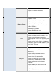
Rear Panel The following table describes the interfaces of the device: Items Description RJ-11 interface, for connecting to the ADSL interface or a splitter through the telephone cable. RJ-45 interface, for connecting to the Ethernet interface of PC Line LAN1, LAN2, Or other Ethernet devices through the Ethernet cable. LAN3, LAN4 Power Power interface, for connecting to the power adapter. Reset to the factory defaults.
The filter must be installed close to the telephone cable. See Figure2. Do not use the splitter to replace the filter. Installing a telephone directly before the splitter may lead to failure of connection between the device and the central office, or failure of Internet access, or slow connection speed. If you really need to add a telephone set before the splitter, you must add a micro filter before a telephone set.
9.
10. LAN Configuration This page shows current LAN configuration.
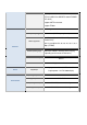
Fields in this screen are the following: Field Description IP Address IP address the LAN hosts can use to identify the LAN port of its device. Subnet Mask LAN sub network mask. Secondary IP MAC Address Control Apply Changes Add Secondary IP (or emergency) and mask. Access control based in MAC address at LAN level. If selected, one MAC included in the list will have access. Click here to keep settings temporarily.
11. Wireless Configuration There are five sub-menus for Wireless configuration: [Basic Settings], [Advance Settings], [Security], [Access Control] and [WPS]. 11.1. Basic Settings This page is used to configure the parameters for wireless LAN clients who may connect to your Access Point. Please refer to the section – Basic settings for details. Fields in this page: Field Description Disable Wireless LAN Check it to disable the wireless function for ADSL modem.
Identifier. Channel Number Drop-down menu that allows selection of specific channel. Radio Power The maximum output power: 15mW, 30mW or 60mW. Function buttons in this page: Associated Clients Click it will show the clients currently associated with the ADSL modem. Apply Changes Change the settings. New parameters will take effect after save into flash memory and reboot the system 11.2. Advanced Settings This page allows advanced users who have sufficient knowledge of wireless LAN.
Field Description Authentication Type Open System: Open System authentication is not required to be successful while a client may decline to authenticate with any particular other client. Shared Key: Shared Key is only available if the WEP option is implemented. Shared Key authentication supports authentication of clients as either a member of those who know a shared secret key or a member of those who do not. IEEE 802.
Preamble Type The Preamble Type defines the length of the CRC (Cyclic Redundancy Check) block for communication between the AP and mobile wireless stations. Make sure to select the appropriate preamble type. Note that high network traffic areas should use the short preamble type. CRC is a common technique for detecting data transmission errors. Broadcast SSID If this option is enabled, the device will automatically transmit their network name (SSID) into open air at regular interval.
Fields in this page: Field Description Encryption There are 4 types of security to be selected. To secure your WLAN, it’s strongly recommended to enable this feature. WEP: Make sure that all wireless devices on your network are using the same encryption level and key. Click Set WEP Key button to set the encryption key. WPA (TKIP): WPA uses Temporal Key Integrity Protocol (TKIP) for data encryption.
WPA Authentication There are 2 types of authentication mode for WPA. code WPA-RADIUS: WPA RADIUS uses an external RADIUS server to perform user authentication. To use WPA RADIUS, enter the IP address of the RADIUS server, he RADIUS port (default is 1812) and the shared secret from the RADIUS server. Please refer to “Authentication RADIUS Server” setting below for RADIUS setting. The WPA algorithm is selected between TKIP and AES, please refer to “WPA cipher Suite” below.
Fields in this page: Field Description Wireless Access Control Mode The Selections are: Disable Disable the wireless ACL feature. Allow Listed When this option is selected, no wireless clients except those whose MAC addresses are in the current access control list will be able to connect (to this device). Deny Listed When this option is selected, all wireless clients except those whose MAC addresses are in the current access control list will be able to connect (to this device).
Click to add this entry into the Current Access Control List. Reset It restores the original values The Current Access Control List lists the client MAC addresses. Any wireless client with its MAC address listed in this access control list will be able to connect to the device. You can select the entries at the Select column and apply to the following function buttons. Function buttons for the Current Access Control List: Delete Selected Delete the selected entries from the list. Delete All Flush the list.
Fields in this page: Field Description Disable WPS Check to disable the Wi-Fi protected Setup. WPS Status When AP’s settings are factory default (out of box), it is set to open security and un-configured state. “WPS Status” will display it as “UnConfigured”. If it already shows “Configured”, some registrars such as Vista WCN will not configure AP. Users will need to go to the “Backup/Restore” page and click “Reset” to reload factory default settings. Self-PIN Number “Self-PIN Number” is AP’s PIN.
Click to regenerate the Self-PIN Number. Start PBC Click to start the Push Button method of WPS. Apply Changes Click to commit changes. Reset It restores the original values. Start PIN Click to start the PIN method of WPS. 12. WAN Configuration There are three sub-menus for WAN configuration: [Channel Comfit], [ATM Settings], and [ADSL Settings]. 12.1. Channel Configuration ADSL modem/router comes with 8 ATM Permanent Virtual Channels (PVCs) at the most.
Function buttons in this page: Add Click Add to complete the channel setup and add this PVC channel into configuration. Modify Select an existing PVC channel by clicking the radio button at the Select column of the Current ATM VC Table before we can modify the PVC channel. After selecting a PVC channel, we can modify the channel configuration at this page. Click Modify to complete the channel modification and apply to the configuration.
Fields in this page: Field Description VPI Virtual Path Identifier. This is read-only field and is selected on the Select column in the Current ATM VC Table. VCI Virtual Channel Identifier. This is read-only field and is selected on the Select column in the Current ATM VC Table. The VCI, together with VPI, is used to identify the next destination of a cell as it passes through to the ATM switch.
SCR Sustained Cell Rate, measured in cells/sec., is the average cell rate over the duration of the connection. MBS Maximum Burst Size, a traffic parameter that specifies the maximum number of cells that can be transmitted at the peak cell rate. Function buttons in this page: Apply Changes Set new PVC QoS mode for the selected PVC. New parameters will take effect after save into flash memory and reboot the system. See section “Admin” for save details. Undo Discard your settings. 12.3.
G.lite : G.992.2 Annex A G.dmt : G.992.1 Annex A T1.413 : T1.413 issue #2 ADSL2 : G.992.3 Annex A ADSL2+ : G.992.5 Annex A AnnexL Option Enable/Disable ADSL2/ADSL2+ Annex L capability. AnnexM Option Enable/Disable ADSL2/ADSL2+ Annex M capability. ADSL Capability “Bit-swap Enable” : Enable/Disable bit-swap capability. “SRA Enable” : Enable/Disable SRA (seamless rate adaptation) capability.
Fields in this page: Field Description IP Pool Range Specify the lowest and highest addresses in the pool. Max Lease Time The Lease Time is the amount of time that a network user is allowed to maintain a network connection to the device using the current dynamic IP address. At the end of the Lease Time, the lease is either renewed or a new IP is issued by the DHCP server. The amount of time is in units of seconds. The default value is 86400 seconds (1 day). The value –1 stands for the infinite lease.
Set new DHCP server configuration. New parameters will take effect after save into flash memory and reboot the system. See section “Admin” for save details.
Fields in this page: Field Description Option 60 To identify the vendor and functionality of a DHCP client. The information is a variable-length string of characters or octets which has a meaning specified by the vendor of the DHCP client.
13.2.1. DNS Server This page is used to select the way to obtain the IP addresses of the DNS servers. Fields in this page: Field Description Attain DNS Automatically Select this item if you want to use the DNS servers obtained by the WAN interface via the auto-configuration mechanism. Set DNS Manually Select this item to configure up to three DNS IP addresses. Function buttons in this page: Apply Changes Set new DNS relay configuration.
13.2.2. Dynamic DNS Each time your device connects to the Internet, your ISP assigns a different IP address to your device. In order for you or other users to access your device from the WAN-side, you need to manually track the IP that is currently used. The Dynamic DNS feature allows you to register your device with a DNS server and access your device each time using the same host name. The Dynamic DNS page allows you to enable/disable the Dynamic DNS feature.
Add Click Add to add this registration into the configuration. Remove Select an existing DDNS registration by clicking the radio button at the Select column of the Dynamic DNS Table. Click Remove button to remove the selected registration from the configuration. 13.3. Access Control 13.3.1. ACL The Access Control List (ACL) is a list of permissions attached to the DSL device. The list specifies who is allowed to access this device.
IP Address Enter the IP address that allows access to this device.
13.3.2. IP/Port Filtering Firewall contains several features that are used to deny or allow traffic from passing through the device. Fields on the first setting block: Field Description Outgoing Default Action Specify the default action on the LAN to WAN forwarding path. Incoming Default Action Specify the default action on the WAN to LAN forwarding path. Fields on the second setting block: Field Description Rule Action Deny or allow traffic when matching this rule.
Src IP Address The source IP address assigned to the traffic on which filtering is applied. Src Subnet Mask Subnet-mask of the source IP. Src Port Starting and ending source port numbers. Dst IP Address The destination IP address assigned to the traffic on which filtering is applied. Dst Subnet Mask Subnet-mask of the destination IP. Dst Port Starting and ending destination port numbers.
13.4.1. Virtual Server 13.4.2.
13.4.3. NAT Forwarding 13.4.4.
13.5. Priority queue In this page, you can configure the QoS preference list. Follow instructions in the page to configure. 13.6.
13.7. Traffic Shaping In this page you can apply Traffic Shaping for the IP traffic control.
13.8. MAC Filtering The MAC filtering feature allows you to define rules to allow or deny frames through the device based on source MAC address, destination MAC address, and traffic direction. Fields on the first setting block: Field Description Outgoing Default Policy Specify the default action on the LAN to WAN bridging/forwarding path. Incoming Default Policy Specify the default action on the WAN to LAN bridging/forwarding path.
Direction Traffic bridging/forwarding direction. Src MAC Address The source MAC address. It must be xxxxxxxxxxxx format. Blanks can be used in the MAC address space and are considered as don’t care. Dst MAC Address The destination MAC address. It must be xxxxxxxxxxxx format. Blanks can be used in the MAC address space and are considered as don’t care. Function buttons for this second setting block: Add Click to save the rule entry to the configuration.
13.10. URL BLOCK In this page you can configure the FQDN (Fully Qualified Domain Name) to which you want to block access. For instance, for the PC named “serv1”, and the domain “bar.com”, you can block access to URL “serv1.bar.com”. you can also block through key word .
13.11. DoS Setting This page allows you to prevent form external attacks. 13.12. IGMP Proxy Multicasting is useful when the same data needs to be sent to more than one hosts. Using multicasting as opposed to sending the same data to the individual hosts uses less network bandwidth. The multicast feature also enables you to receive multicast video stream from multicast servers. IP hosts use Internet Group Management Protocol (IGMP) to report their multicast group memberships to neighboring routers.
The IGMP Proxy page allows you to enable multicast on WAN and LAN interfaces. The LAN interface is always served as downstream IGMP proxy, and you can configure one of the available WAN interfaces as the upstream IGMP proxy. Upstream: The interface that IGMP requests from hosts is sent to the multicast router. Downstream: The interface data from the multicast router are sent to hosts in the multicast group database.
13.13. RIP RIP is an Internet protocol you can set up to share routing table information with other routing devices on your LAN, at your ISP’s location, or on remote networks connected to your network via the ADSL line. Most small home or office networks do not need to use RIP; they have only one router, such as the ADSL Router, and one path to an ISP. In these cases, there is no need to share routes, because all Internet data from the network is sent to the same ISP gateway.
Apply Changes Click to save the setting of this setting block to the system configuration Fields on the second setting block: Field Description Interface The name of the interface on which you want to enable RIP. Receive Mode Indicate the RIP version in which information must be passed to the DSL device in order for it to be accepted into its routing table. Send Mode Indicate the RIP version this interface will use when it sends its route information to other devices.
Fields in this page: Field Description Ageing Time Set the Ethernet address ageing time, in seconds. After [Ageing Time] seconds of not having seen a frame coming from a certain address, the bridge will time out (delete) that address from Forwarding Database (fdb). 802.1d Spanning Tree Enable/disable the spanning tree protocol Function buttons in this page: Apply Changes Save this bridge configuration. New configuration will take effect after saving into flash memory and rebooting the system.
14.3. Routing The Routing page enables you to define specific route for your Internet and network data. Most users do not need to define routes. On a typical small home or office LAN, the existing routes that set up the default gateways for your LAN hosts and for the DSL device provide the most appropriate path for all your Internet traffic. On your LAN hosts, a default gateway directs all Internet traffic to the LAN port(s) on the DSL device.
Fields in this page: Field Description Enable Check to enable the selected route or route to be added. Destination The network IP address of the subnet. The destination can be specified as the IP address of a subnet or a specific host in the subnet. It can also be specified as all zeros to indicate that this route should be used for all destinations for which no other route is defined (this is the route that creates the default gateway). Subnet Mask The network mask of the destination subnet.
Update Update the selected destination route on the Static Route Table. Delete Selected Delete a selected destination route on the Static Route Table. Show Routes Click this button to view the DSL device’s routing table. The IP Route Table displays, as shown in Figure. 14.4. UPnP Configuration Universal Plug and Play (UPnP) defines protocols and common procedures to guarantee the interoperability among PCs allowed in network, applications and wireless devices.
14.5. SNMP Configuration Simple Network Management Protocol (SNMP) is a troubleshooting and management protocol that uses the UDP protocol on port 161 to communicate between clients and servers. The DSL device can be managed locally or remotely by SNMP protocol.
Field Description System Description System description of the DSL device. System Contact Contact person and/or contact information for the DSL device. System Name An administratively assigned name for the DSL device. System Location The physical location of the DSL device. System Object ID Vendor object identifier. The vendor’s authoritative identification of the network management subsystem contained in the entity. Trap IP Address Destination IP address of the SNMP trap.
14.7. Other advanced configuration This page allows configuring the modem in Half Bridge mode. If it is enabled the modem will turn to be visible. The DHCP will duplicate the WAN IP from its local ISP to your PC and only one PC of the local network will be allowed to connect to internet.
14.8.
15. Diagnostic This ADSL device supports some very useful diagnostic tools: 15.1. Ping Once you have your DSL device configured, it is a good idea to make sure you can ping the network. A ping command sends a message to the host you specify. If the host receives the message, it sends messages in reply. To use it, you must know the IP address of the host you are trying to communicate with and enter the IP address in the Host Address field.
15.2. Traceroute Through this tool you can track the packets going from one network point to the other. 15.3. ATM Loopback In order to isolate the ATM interface problems, you can use ATM OAM loopback cells to verify connectivity between VP/VC endpoints, as well as segment endpoints within the VP/VC. ATM uses F4 and F5 cell flows as follows: • • F4: used in VPs F5: used in VCs An ATM connection consists of a group of points.
16. Admin 16.1. Commit / Reboot Whenever you use the Web configuration to change system settings, the changes are initially placed in temporary storage. These changes will be lost if the device is reset or turn off.
16.2. Backup/Restore This page allows you to backup and restore your configuration into and from file in your host.
16.3. Password Setup The first time you log into the system, you use the default password. In this page you can change the Access details if needed. Fields in this page: Field Description User Name Selection of user levels are: admin and user. Old Password Enter the old password for this selected login. New Password Enter the new password here. Confirmed Password Enter the new password here again to confirm. 16.4.
16.5. TR-069 Config. TR-069 is a protocol for communication between a CPE and Auto-Configuration Server (ACS).
Fields in this page: ACS Field Description URL ACS URL. For example, http://10.0.0.1:80 https://10.0.0.1:443 User Name The username the DSL device should use when connecting to the ACS. Password The password the DSL device should use when connecting to the ACS.