
User manual


Rear Panel
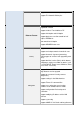
The following table describes the interfaces of the device:
I
tems
Descri
p
tion
Line
RJ-11
interface,
for
connecting
to
the
ADSL
interface
or
a splitter
through
t
he
telephone
ca
bl
e.
LAN1,
LAN2,
LAN3,
LAN4
RJ-45
interface,
for
connecting
to
the
Ethernet
interface
of
PC
Or
other
Ethernet
devices
through
the
Ethernet
cable.
Power
Power
interface,
for
connecting
to
the
power
adapter.
Reset
Reset
to
the
factory
defaults.
To
reset
to
the
factory
defaults, keep
the
device
powered
on
and
push
a
paper
clip
in
to
the hole
for
over
3
seconds.
Then
release
it,
the
configuration
is reset
to
the
factory
defaults.
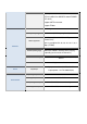
WLAN/WPS
Button to enable and disable Wireless interface and establish WPS
connection
Power
switch,
power
on
or
power
off
the
device.
7.
Hardware Installation
Following figure shows the connection of the router to the different elements of the network.
Connection diagram (Connecting a telephone set before the splitter)
Note: