FLAMINGOS at the KPNO 4-m An Observer's Guide Nick Raines & Richard Elston Version 2.34, 2006 April 04 (4m figure © A. R. King/NOAO/AURA/NSF) FLAMINGOS@4-m, Ver. 2.
Contents I. FLAMINGOS + KPNO 4-m Overview II. Starting FLAMINGOS III.Nightly Startup Tasks A. FLAMINGOS Setup B. Startup on the Sky IV.Imaging with FLAMINGOS A. Overview B. Wheel Setup for Imaging C. Configuring an Exposure D. Taking an Image at a Single Pointing E. Taking Dithered Images F. Offsetting the Telescope from Flamingos1a or 1b G. Taking Darks V. Taking Spectra with FLAMINGOS A. Overview B. Long Slit Alignment C. MOS Plate Alignment D. Taking Spectra Once the Slit or MOS plate is Aligned E.
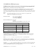
I. FLAMINGOS + KPNO 4-m Overview FLAMINGOS is the FLoridA Multi-object Imaging Near-ir Grism Observational Spectrometer. This manual provides the user with a good portion of the tools needed to successfully take data with FLAMINGOS at the KPNO 4-m telescope. A knowledge of basic unix commands is assumed. FLAMINGOS is comprised of two cryogenic dewars. The MOS dewar, closest to the telescope backplane, contains a wheel which can position 11 slit plates in the Cassegrain focal plane.
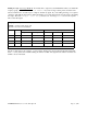
Spectral Characteristics Filter / Grism Combination JH-bandpass + JH-grism HK-bandpass + HK-grism JH-bandpass + HK-grism Band R = λ / δλ Dispersion R = λ / δλ (2 pix slit) (Å/pixel) (3 pix slit) J 1400 4.68 960 H 1800 4.68 1250 970 8.55 650 K 1300 8.55 865 J (2nd order) 1500 4.
-h option is for human readable format, and it prints values out with KB, MB, and GB suffixes as appropriate). Data Analysis: An IRAF session will be running on flamingos1a. Simple analysis tasks such as quick image arithmatic, image stacking, and image statistics can be performed with it while taking data. There are no pipeline reduction packages installed on flamingos1a for imaging or spectroscopy data.
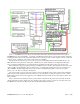
Figure 1. FLAMINGOS Functional Diagram. The relative layout and connnections between the various parts of FLAMINGOS are shown shematically. A schematic of the MOS and Camera dewars is shown in the middle of the figure, including the relative layout of the 5 internal mechanisms above the detector array, and the elements of the two electronics racks are shown on either side of the dewars, much as they are in actuality.
Halting A Script: Never type Ctrl-C. It is much safer to suspend a job with Ctrl-Z. Then you can kill the script by typing jobs, and kill -9 %. If you are moving a wheel, please just wait for the wheel to finish motion, and the script to complete, and then try again. If you are taking an image or a sequence of images, wait until the script starts counting the number of seconds elapsed in the exposure before suspending the script. Then run ufstop.pl -clean -stop, and start over.
II.Starting FLAMINGOS When you arrive at the 4-m telescope, you may have to bring up the FLAMINGOS windows and initialize the system (it should have been done during the checkout night). Steps 1–6 of this procedure will hopefully only need to be done once at the beginning of your run; however, you may need to repeat this process during the course of your observing time if you get logged out, or if the system crashes. The observer interface is from the tan console.
7. You are now ready to initialize FLAMINGOS! This is done by running the command initflam.pl. This script initializes agents and displays the following windows: Temperature Daemon - This daemon reads temperatures from two different sensors in FLAMINGOS with the following output written to the screen: UFLakeShore208Agent::ancillary >new reading:(2002:170:05:24:06.920436) 1,75.67 6,82.73 You should always keep an eye on the array temperature ( ~76 K, in the example above where it says 1, 75.
During the first execution of initflam.pl, you will be asked at multiple points whether you wish to continue. In general, if the daemon windows say listening on port, startup has been successful and you should answer y (for yes). If you are re-running initflam.pl after rebooting MCE4 after a detector controller crash (cf. § VII.
III.Nightly Startup Tasks A. FLAMINGOS Setup We recommend that you complete the following list prior to each night's observing. 1. Restart all daemons, temperature logging and temperature plotting windows. Please see the notes at the end of the previous section. The daemons should all be Quit (not Closed, as this just minimizes them), and initflam.pl immediately re-run, in order to restart the daemons. 2. Fill Both Dewars.
should have ~5 GB of space. However, note that the image acquistion scripts will complain on each and every image if the disk space is is ≥ 93% full, and will refuse to take any more data if the disk is ≥ 97% full. Start the autocopy script. After the image is created on flamingos1a a file with the suffix unlock will be created. The autocopy script monitors the night directory, and when an unlock file appears it copies the corresponding image to nutmeg and deletes the unlock file.
Opening the telescope and dome. Preliminary pointing check of a bright star on the North Port TV camera. The star should be located on the grease pencil x-mark on the monitor that corresponds to the FLAMINGOS hot spot. Focus telescope on North Port TV camera (in direct video mode, not on the guide camera). Measure seeing.
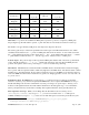
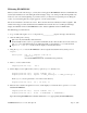
detail the use of both here. The flmntools tasks fwcheck and fwscan take differences of images, and then run SExtractor on the central 1250 × 1250 pixel region to determine the average FWHM; sources brighter than 10,000 ADU in the difference image are ignored and objects with FWHM < 1.3 pixels are rejected as cosmic ray hits.
3 4 5 6 7 8 9 2 3 4 5 6 7 8 0.82'' 0.88'' 0.91'' 0.79'' 0.86'' 0.76'' 0.82'' 0.82'' 0.87'' 0.92'' 0.80'' 0.85'' 0.76'' 0.81'' 0.77'' 0.81'' 0.82'' 0.74'' 0.79'' 0.70'' 0.78'' 42 45 51 39 48 45 43 fwcheck differences two frames, computes the FWHM, displays the difference frame in buffer 4 of ds9, and finishes with an imexam cursor on the image.
IV.Imaging with FLAMINGOS A. Overview FLAMINGOS may be used for imaging through J-, H-, K-, and Ks-band filters. Sky emission in these bands is variable and may be bright3. Exposure times are kept reasonably short as a result and guiding is not required. The general observing procedure is to point the telescope in a dither pattern about the source. FLAMINGOS has a dither script with several different dither patterns available.
On the FLAMINGOS command line: config.dither.kpno.pl config.exposure.pl Use to setup a sequence of images dithered about a common pointing center. Set filename, storage directory, exposure time, and number of reads, as well as several descriptive fields. config.filter.grism.decker.wheels.pl Insert filter, grism and appropriate baffle on decker wheel. config.mos.wheel Use to select the MOS wheel imaging hole. dither.source.kpno.pl Executes data acquisition in the selected pattern. fast.singleimage.
of valid positions. Note that position 0 for each wheel is the home position. As with the MOS script, the script will print out a detailed information window, the last bit of which shows the desired move. Answering y at this point will issue the wheel motion command. For both scripts the wheel motion status will be queried approximately every 5 seconds, and the result will be printed to the screen.
WEATHER WIND the actual present bias value hit the Update All button on the UFSTATUS GUI. A numerical descriptor of common environmental conditions (1=photometric, 2=thin cirrus, 3=broken clouds, 4=overcast, 5=snowing, 6=fog). A numerical range descriptor of the wind speed (1=calm, 2=low, 3=moderate, 4=high, 5=closed). After prompting you for all of these parameters, config.exposure.pl will ask if you want to change the bias. If you do it will automatically run the script set.bias.pl.
pointing coordinates, and dither about that new position. See the next section on offseting the telescope from the FLAMINGOS command line. You can monitor seeing variations and any focus drift if you continuously use fwscan while the dither pattern executes; just start using it after the first two images have read out. F.
~4mguest/bin/Example.many.scripted.darks.csh Note that the blank lines are very important! Also, be very certain to check later that the script completed successfully; cf. § VIII. Troubleshooting for possible failure modes, such as bad reads, scrambled images, zero frames, and MCE4 hangs. FLAMINGOS@4-m, Ver. 2.
V.Taking Spectra with FLAMINGOS A. Overview FLAMINGOS may be used for obtaining long slit or multi-object slit spectra; please see Section I. FLAMINGOS + KPNO 4-m Overview for resolving powers within selected passbands. As with imaging, the sky emission is variable and bright. It is necessary to subtract this contribution from the target spectrum. To this end, observers generally dither the target up and down the slit.
These may be done in the afternoon. The following list of commands is used for long slit and MOS plate spectroscopy: On the flamingos command line: config.exposure.pl config.filter.grism.decker.wheels.pl config.mos.wheel.pl config.mos.dither.kp4m.pl dither.mos.kp4m.pl set.bias.pl tweak.decker.pl tweak.mos.pl Setup the filename and exposure time. Use to insert filter and grism and appropriate baffle. Use to insert long slit or MOS plate. Setup the spectroscopy ABBA parameters.
The easiest way to check the straightness of this wide slit is to draw a ds9 ruler parallel to one edge. Then double click on the ruler, to find out the angle. It probably should be within 0.05° of 90°. A more accurate method is to use imexam and j to fit a gaussian to a cross-cut through the slit at two different y-values. Record the fitted peak (x-coordinate) and the y values, and compute the angle arctan(dx / dy) if dx is > 1.5 pixel.
We typically use alignment star boxes that are 24 – 30 pixels wide. It is very important that this parameter be set to within a few pixels of the actual values. L 2. rot_4m M This is listed as the 4-m rotation offset, and it should directly correspond to the instrument position angle. We have experimentally determined that it works for position angle of 90 degrees: If ROT_PA = 90: set rot_4m = -90. N Running xbox causes a graphics terminal to pop up.
The images are usually kept in /data/4mguest/Maskfiles/. Flip and rotate until the image WCS matches that of a raw FLAMINGOS frame. Turn on tiling, with a vertical orientation; tiling of buffers 1, 2, and 3 is useful. Hide buffer 4. 5. Acquire target on FLAMINGOS in Ks filter. Set exposure time to pick out aligment targets. Try an exposure time of 10 – 30 seconds if they are bright, but do not let them saturate. You may need to use much longer itimes (60 – 120 seconds) if they are very faint.
Type :go An xgterm window with two cross-cut plots through the box, one each for the x and y axes will pop up. Type q to step through each of the boxes in the graphics window. If the box center is not clearly detected, use the f key to force the center, and g to force the signal threshold. After the last box it will pop up a window showing graphically how much each box must move to acquire the aligment target. Type q again.
MOS plate data. Walking up the slit: We usually move up the slit in steps of 10" for a total of 5-7 positions. Use singleimage.pl to take an image by hand at every location. Use relative.offset.kpno.pl to move the star up and down the slit (while continuing to guide). Setup to execute a dithered ABBA script: 1. 2. 3. 4. Zero the telescope offsets; type clear.offsets.kpno.pl and type y at the prompt. Insert filter and grism combination with config.filter.grism.decker.wheels.pl.
projector have absorption bands near 2.3 microns which will show up in the flatfield spectra. Therefore, an alternative approach to obtaining flats is to observe the inside of the dome using the flatfield lights mounted at the end of the telescope. Usually only one set of wavelength calibrations is needed per target; alternatively the OH sky lines may be used for wavelength calibration, if they are not saturated.
We usually use only sky lines (OH) for wavelength calibration in the HK-band. If you wish to resume guiding on the science target for additional observations without rechecking the alignment (this may or may not work): 1. Have the telescope operator do the following: Turn off calibration lamps. Take out the Comps mirror (put it back to the THRU position). Resume guiding. N.B.: When guiding is suspended the guide star may move slightly out of the guide box.
VI.Shutting Down at the End of the Night At the end of a long and (we hope!) productive night of observing, there is a small sequence of things that need to be done. In order, they are: 1. Move the wheels to their resting positions. Using the scripts config.mos.wheel.pl and config.filter.grism.decker.wheels.pl send the MOS wheel to imaging, the Decker wheel to imaging, the Filter wheel to J, and the Grism wheel to true_dark. 2. Take any necessary dark frames.
VIII.Troubleshooting 1) Problem: The image looks funny. You can see all 32 amplifiers, and the signal level is ~58,000 ADU; the preceeding or following image(s) has 0 counts. Solution: This is a hardware problem related to electrical noise causing an early readout of the detector. In imaging mode MCE4 reads the array once, and then lets it integrate before reading it again (cf. Appendix 2: Readout Schematic). The final image written to disk is the difference of these two images.
motor controller, and the MCE4 array controller) which accept commands via serial ports. The perle has one serial port connection for each device. Commands from the software daemons running on flamingos1a are received by the perle via an ethernet connection, and then passed to the correct device. Troubleshooting several types of problems involves deciding if the problem is intrinsic to the device, or to the communication via the perle itself. a) Problem: The image has not read out.
Internal Temperature True RMS current: Maximum Detected: 1.6 Amps 1.7 Amps Internal Temperature: 18.5 C Circuit Breaker: On Selection Number 1 Outlet Name mce4 Outlet Number 4 Power Status On Type "Help" for a list of commands RPC-3>reboot 1 (Now it counts down for 10 seconds before applying the power). ..RPC-3>logout Now run initflam.pl at the flamingos1a prompt. You do not need to close any of the daemons to rerun initflam.pl for this problem. At the start, initflam.
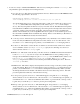
Figure 2. Fiber optic converter boxes below MCE4 (left panel) and below perle (right panel) c) Problem: The image acquisition counts past the exposure time without reading out an image. Solution: This problem rarely happens anymore. With our previous slower version of flamingos1a, it would sometimes take an extra 5 to 10 seconds to finish reordering the pixels, i.e., applying the look up table, or LUT, before it writes the image to disk.
saying that the time for the wheel's motion to complete has expired. The default algorithm for motion of the wheels is that they first go to the home position, tell the controller to zero the position, and then move to the demanded position. We refer to this as a home-type of limit, or limit switch. We usually run the MOS wheel in an alternative mode refered to as a home-type of nearhome.
IX.Contacts & Further Information 1. Dick Joyce, Ron Probst, and/or Nick Raines will help new observers during their first night of observing with FLAMINGOS at the 4-m. If simple questions arise during the run, please address them first to Dick or Ron, and then to Nick. Their contact information is listed below. Richard Elston, University of Florida, FLAMINGOS PI office: 352-392-2052 elston@astro.ufl.edu Nick Raines, University of Florida, FLAMINGOS support scientist office 352-392-2052, ext.
Appendix 1: FLAMINGOS Command Listing and Partial Description of Function A. Basic Instrument Configuration Commands config.exposure.pl Sets object, filebase, orig_dir, exp_time. config.filter.grism.decker.wheels.pl config.mos.wheel.pl initflam.pl set.bias.pl set.exposuretime.pl set.filename.pl Setup and move Filter, Grism and Decker wheels. Setup and move the MOS wheel. Starts daemons and setup MCE4 array controller. Imaging use bias = 1.0 V; Spectroscopy use bias = 0.75 V.
F. Resetting the Array Controller (MCE4), the Motor Controller, and the Iocomm From flamingos1a: 1. telnet baytech userid: mce4pow, motorpow, or perlepow password: __________ (For telnet from a Kitt Peak machine, the baytech's name is flmn-4m-p). 2. reboot 1 3. logout 4. If you rebooted the perle, close all daemons (the TEMPS, MOTOR, and MCE4 xterm windows), otherwise leave them open. 5. initflam.pl G.
H. Instrument Engineering Commands center.of.rotation.pl config.location.pl Determine the center of rotation from 3 points. Copies the correct Flamingos.fitsheader for a telescope. engineering.config.home.type.wheels.pl Sets Limit Switch or Near Home wheel motion. engineering.config.mst.pl Sets milliseconds vs. seconds timer usage. engineering.config.output.pl Various settings (unlock file, talk to TCS, png image, etc.). engineering.ct10.singleimage.pl Output the first read of a CDS read. engineering.
Appendix 2: Readout Schematic Figure 3 Array Readout Timing. All 4 quadrants of the array are read out simultaneously; within one quadrant all 8 amplifiers are read out, with pairs of amplifiers multiplexed down into one A/D input. Thus in a frame time of 1.33 seconds 1024 × 256 pixels are read out. The image delivered by MCE4 for a CDS frame is the difference image from two nondestructive reads of the array; the timing for a CDS frame with integration time of 6 seconds is shown.
Appendix 3: XBOX Default Parameter List for Instrument at PA = 90 degrees PACKAGE = ucsclris TASK = xbox image input (stars (nxbox (nybox (xsz (ysz (fwhm tel (rotdir rot_2m xrot_2m yrot_2m invert2m rot_4m xrot_4m yrot_4m invert4m MMT_rot MMT_xrot MMT_yrot MMT_inve GemS_rot GemS_xro GemS_yro GemS_inv (xoff (yoff (def_ref (def_err (niter (box_siz new_x_fw new_y_fw vmag wt (coord (mode = = = = = = = = = = = = = = = = = = = = = = = = = = = = = = = = = = = = = = target.
Appendix 4: Additional Notes on MOS Plates An example MOS plate for use at the 4-m is shown adjacent, in Figure 4. It is approximately full size (~105 mm in length). The sizes of the slits and alignment boxes are the same size in pixels for both telescopes. The slitlets are 3 pixels (0.9" at the 4-m) wide, with a minimum length of approximately 30 to 40 pixels (9" to 12" at the 4-m). The alignment boxes are 25 to 30 pixels (7.5" to 9" at the 4-m) on a side.
Appendix 4: Additional Notes on MOS Plates: A Figure of the MOS Wheel, Useful When Loading Plates MOS Position PA B ______ D ______ F ______ H ______ K ______ L ______ Name ____________________ ____________________ ____________________ ____________________ ____________________ ____________________ MOS Position PA M ______ N ______ O ______ P ______ Q ______ Name ________________ ________________ ________________ ________________ ________________ Telescope: ___________________________________ Date Loade