FLAMINGOS at the KPNO 4-m An Observer's Guide Dick Joyce, Nick Raines, Richard Elston Version 2.39, 2013 April 23 (4m figure © A. R. King/NOAO/AURA/NSF) FLAMINGOS@4-m, Ver. 2.
Contents I. FLAMINGOS + KPNO 4-m Overview II. Starting FLAMINGOS III.Nightly Startup Tasks A. FLAMINGOS Setup B. Startup on the Sky IV.Imaging with FLAMINGOS A. Overview B. Wheel Setup for Imaging C. Configuring an Exposure D. Taking an Image at a Single Pointing E. Taking Dithered Images F. Offsetting the Telescope from Flamingos1a or 1b G. Taking Darks H. Dome Flats I. Custom Scripts V. Taking Spectra with FLAMINGOS A. Overview B. Preliminary Setup C. Long Slit and MOS Plate Alignment D.
I. FLAMINGOS + KPNO 4-m Overview FLAMINGOS is the FLoridA Multi-object Imaging Near-ir Grism Observational Spectrometer. This manual provides the user with a good portion of the tools needed to successfully take data with FLAMINGOS at the KPNO 4-m telescope. A knowledge of basic unix commands is assumed. FLAMINGOS is comprised of two cryogenic dewars. The MOS dewar, closest to the telescope backplane, contains a wheel which can position 11 slit plates in the Cassegrain focal plane.
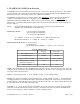
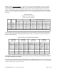
Spectral Characteristics Filter / Grism Combination Band R = λ / δλ Dispersion R = λ / δλ (2 pix slit) (Å/pixel) (3 pix slit) JH + JH-grism J 1400 4.69 960 H 1800 4.69 1250 HK + HK-grism H 970 8.42 650 K 1300 8.42 865 JH+ HK-grism J (2 order) 1500 4.4 1000 nd MOS Plates: 11 positions are available for MOS plates; usually, one position is occupied by a MOS plate containing a single 3 pixel wide long slit; 3 pixel wide slits are customarily used at the 4-m telescope.
Data Analysis: An IRAF session will be running on flamingos1a. Simple analysis tasks such as quick image arithmetic, image stacking, and image statistics can be performed with it while taking data. There are no pipeline reduction packages installed on flamingos1a for imaging or spectroscopy data. If you wish to reduce data simultaneously while taking data, we recommend that you transfer it to one of the MacMinis (usually the one not used for observing) and do so there using the local IRAF package.
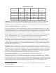
Figure 1: FLAMINGOS Functional Diagram. The relative layout and connections between the various parts of FLAMINGOS are shown schematically. The MOS and Camera dewars are shown in the middle of the figure, including the relative layout of the 5 internal mechanisms above the detector array, and the elements of the two electronics racks are shown on either side of the dewars, much as they are in actuality.
Halting A Script: Never type Ctrl-C. It is much safer to suspend a job with Ctrl-Z. Then you can kill the script by typing jobs, and kill -9 %. If you are moving a wheel, please just wait for the wheel motion to finish and the script to complete before trying again. If you are taking an image or a sequence of images, wait until the script starts counting the number of seconds elapsed in the exposure before suspending the script. Then run ufstop.pl -clean -stop, and start over.
II.Starting FLAMINGOS When you arrive at the 4-m telescope, you may have to bring up the FLAMINGOS windows and initialize the system (this should have been done during the checkout night). The initial steps of this procedure will hopefully only need to be done once at the beginning of your run; however, you may need to repeat this process during the course of your observing time if you get logged out, or if the system crashes. The observer interface at the 4-m has been significantly upgraded.
automatically appear in the upper left corner (or now in the upper small monitor). 6. You are now ready to initialize FLAMINGOS! This is done by running the command ♫ initflam.pl ♫ This script initializes agents and displays the following windows: Temperature Daemon - This daemon reads temperatures from three different sensors in FLAMINGOS with the following output written to the screen: UFLakeShore208Agent::ancillary >new reading:(2002:170:05:24:06.920436) 1,75.67 6,82.73 7,83.
about 30 minutes there will be ~3 points in the Record Temperatures log file, and you can hit the Update button to plot the current temperature. During the first execution of initflam.pl, you will be asked at multiple points whether you wish to continue. In general, if the daemon windows say "listening on port", startup has been successful, and you should answer "y" (for yes). If you are re-running initflam.pl after rebooting MCE4 after a detector controller crash (cf. § VII.
III.Nightly Startup Tasks A. FLAMINGOS Setup We recommend that you carry out the following procedures prior to each night's observing. 1. Restart all daemons, temperature logging and temperature plotting windows. This now seems to be largely unnecessary. If the system is up and running in the afternoon, continue to use it. The daemons should all be Quit (not Closed, as this just minimizes them), and initflam.pl immediately re-run, in order to restart the daemons. 2. Fill Both Dewars.
4. Open the shortcuts menu. Many of the common FLAMINGOS commands which do not require arguments may now be run from a shortcuts menu on the mayall-2 or mayall-3 desktop. Double-click on the FLAMINGOS icon to bring up the menu (Figure 2). In the following, the appropriate button will be noted in square brackets along with the command line input. Figure 2: Command menu on the mayall-2/3 desktop.
are printed out: OBS_TYPE OBJECT FILEBASE ORIG_DIR DATE_OBS EXP_TIME NREADS BIAS WEATHER WIND Type of observation being taken; commonly used keywords are object, standard, flat, dark. Name of object being observed. NOT provided by TCS. Image filename's prefix; the naming convention is filebase.####.fits where the numbers (####) are automatically incremented by the data taking script from 0001 to 9999. Absolute pathname of the directory to which you wish to write data.
9. Execute Mirror Script on Mayall-2/3. Running the mirror script on one of the MacMinis (usually the one not used for observing) will automatically move the data from the flamingos1a data directory to a directory on the MacMini for analysis or archiving on storage media such as a USB drive or DVD. From a terminal on mayall-2 or 3, run % ~/bin/mirror flamingos1a /data/4mguest/
where is the data subdirectory in /data/4mguest on flamingos1a. It is probably safest to use the full path name.4. Ask the telescope operator to Zero the telescope pointing. 5. Verify optical alignment. During the first pointing check of the observing run, it is advisable to take an image of a very bright star way out of focus, to verify that the pupil stop has not been moved, and that the mirror covers and dome are open and positioned properly. You should see a bright donut, with shadows for the secondary and the spider vanes. If the donut is not circular (e.g.
It computes running difference images from which it computes the FWHM. You can use this to monitor the seeing during a sequence of observations. To use this for focus runs, e.g., • • • 4mguest@flmn-4m-1a{19} singleimage.pl 4mguest@flmn-4m-1a{20} relative.offset.kpno.pl 10 0 Ask the operator to increment the focus (50 – 100 units). Repeat these three steps as necessary, offsetting the telescope back and forth between each image.
We frequently monitor the middle dome temperature, but there is also a truss temperature monitor that the telescope operator can read for you. It's advisable to watch the temperature every 30 – 60 minutes, and if necessary adjust the focus on the TV camera. A good starting point for the focus is the chart of f/8 focus vs. truss temperature, on the wall between mayall-2 and mayall-3. A snowflake icon on the mayall-2 and mayall-3 desktops will display the telescope truss temperature.
IV.Imaging with FLAMINGOS A. Overview FLAMINGOS may be used for imaging through the J, H, K, and Ks band filters. Sky emission in these bands is variable and may be bright3. Exposure times are kept reasonably short as a result and guiding is not required. The general observing procedure is to point the telescope in a dither pattern about the source, taking one or more images at each location. FLAMINGOS has a dither script with several different dither patterns available.
On the FLAMINGOS command line: config.dither.kpno.pl config.exposure.pl config.filter.grism.decker.wheels.pl config.rel.mv.filter.grism.decker. wheels.pl config.rel.mv.mos.wheel.pl dither.source.kpno.pl fast.singleimage.pl more.singleimages.pl offset.kpno.pl relative.offset.kpno.pl set.bias.pl set.exposuretime.pl set.filename.pl singleimage.pl Set up a sequence of images dithered about a common pointing center.
printed to the screen. Do not hit the Update All Items button on the UFSTATUS GUI during execution of either of these scripts. It is, however, a good idea to update the GUI after the script has successfully completed. NOTE: It is not possible to move more than one wheel at a time. The only useful dark position is on the Grism wheel; there is a dark position on the Decker wheel, but it does not provide a truly dark condition, since it is not directly in front of the detector.
dither pattern, and it will ask you to type either HOME or CLEAR before beginning to execute the dither pattern. If you have any offsets showing on the TCS, typing HOME will cause the script to dither about the pointing center where the offsets are (0,0), while typing CLEAR will absorb any offsets present into the current pointing coordinates, and dither about that new position (i.e., it will perform a Z of the telescope coordinates).
~4mguest/bin/Example.many.scripted.darks.csh Note that the blank lines are very important! Also, be very certain to check later that the script completed successfully; cf. § VIII. Troubleshooting for possible failure modes, such as bad reads, scrambled images, zero frames, and MCE4 hangs. H. Dome Flats Although most observers use sky flats generated from the target observations, one may take dome flats as a backup.
V.Taking Spectra with FLAMINGOS A. Overview FLAMINGOS may be used for obtaining long slit or multi-object slit spectra; please see § I. FLAMINGOS + KPNO 4-m Overview for resolving powers within selected passbands. As with imaging, the sky emission is variable and bright, and there is additional background in the HK mode from the camera dewar window. It is necessary to subtract this contribution from the target spectrum. This is accomplished by dithering the target up and down the slit.
Figure 4: Schematic of the UF 3pix long slit (left) and NOAO slit (right). The acquisition box for the NOAO slit is 10 arcsec square at the 4-m. The two slits are each 60 arcsec long, centered 60 arcsec on either side of the center of the mask. The general outline for spectral observations is: 1. Set Instrument Position Angle (PA) to match the slit PA. 2. Verify telescope pointing on a SAO or Fixed Bright star close to target position. 3.
The following commands are used for long slit and MOS plate spectroscopy: On the Flamingos command line: config.exposure.pl config.filter.grism.decker.wheels.pl config.rel.mv.filter.grism.decker. wheels.pl config.rel.mv.mos.wheel.pl config.mos.dither.kp4m.pl dither.mos.kp4m.pl set.bias.pl tweak.decker.pl tweak.mos.pl At the iraf cl prompt: imexam xbox Set up the filename and exposure time.
C. Long Slit or MOS Plate Alignment 1. Set instrument PA before acquiring target. • This must be done first, as the telescope must be at zenith in order to move the rotator. • For safety reasons, the telescope operator must make the rotation from the Cassegrain Cage. • Run config.mos.dither.kp4m.pl, and set the parameter ROT_PA to the new value, so the WCS compass arrows will display correctly in ds9 and the dither motion will be in the correct direction 2. [MOS]Load image of science field.
9. [NOAO slit in mask] Center the target. • The Decker wheel should already be in the mos position. • Move the slit mask into the beam using config.rel.mv.mos.wheel.pl [Move MOS Wheel] • Take an image; one should see the target in the alignment box in the mask • Use relative.offset.kpno.pl or ask the telescope operator move the telescope to center the star in the alignment box. This may take several iterations. • Offset the telescope 60 arcsec in the direction of the rotator position angle.
estimated location of the box along the bottom of each cut, along with a horizontal threshold level through the cut, and a vertical line indicating the estimated location of the peak of the alignment target; the first time through there likely will be no targets in the boxes, and the line will be centered on a noise peak.
If targets are faint, you may need to offset a small amount (20") and work with a scaled difference image. See the comments at the end of this section on how best to do this. Integration times may need to be increased, too. 6. Have the telescope operator adjust focus on the TV camera, • The guide camera should be confocal with FLAMINGOS, and should give a good starting focus.
16.Remeasure the boxes with imexam and make a new box file, if a tweak.mos.pl was required previously. 17.Run xbox on the latest image: • Set the parameter image to the new mask image • Set the parameter input to the new box file • Set the parameter stars to be blank • Type :go, and run through each of the graphics windows. Type q if the correct peak has been detected, otherwise move the cursor to the correct peak, and type the f key to select it. 18.
Make certain the PA is correct. Set M_RPTPAT to the number of times to repeat the pattern. Set M_THROW, the distance in arcseconds between the A & B beams (which are symmetrically offset about the telescope zero point). For MOS observations we use 4". • If USEMNUDG = 1, the ABBA pattern will be offset along the slit by M_NDGSZ (in arcseconds) on pattern repeats. For MOS observations we use M_NDGSZ = 0.3. Alternatively, one can execute the dither sequence with one ABBA pattern at a time, and use relative.
science target spectra. The alignment of the slit, filter and grism should not have been changed from that used for the science target. It should take 5 – 10 minutes to complete. 1. Have the telescope operator do the following: • Pause guiding. To do so, just hit the OFF button for the guider. • Turn down the guide camera gain. • Select the Comps mirror position. • Select the Dim Quartz lamp at 100% power. 2. Set filename and exposure time. Use config.exposure.pl.
• Turn on the flatfield projector on the telescope using the Bright lamps at maximum setting. 2. Set filename and exposure time. Use config.exposure.pl. • Integration times of 10 – 30 s should suffice for JH- and HK-band spectroscopy. • Take a test exposure (singleimage.pl). The counts should be < 25,000 ADU for wavelengths < 2.4 μm. • With 30 second integration times, it is possible to do 8 reads, if you can accept the little bit of extra overhead. • For longslit observations, one can use the White Spot.
VI.Shutting Down at the End of the Night At the end of a long and (we hope!) productive night of observing, there are a few things that need to be done. In order, they are: 1. Move the wheels to their default positions. Using the scripts config.rel.mv.mos.wheel.pl [Move MOS Wheel] and config.rel.mv.filter.grism.decker.wheels.pl [Move Wheels] send the MOS wheel to imaging, the Decker wheel to imaging, the Filter wheel to J, and the Grism wheel to true_dark. 2. Take any necessary dark frames.
VIII.Troubleshooting 1) Problem: The image looks funny. You can see all 32 amplifiers, and the signal level is ~58,000 ADU; the preceding or following image(s) has 0 counts. Solution: This is a hardware problem related to electrical noise causing an early readout of the detector. In imaging mode MCE4 reads the array once, and then lets it integrate before reading it again (cf. Appendix 2: Readout Schematic). The final image written to disk is the difference of these two images.
casts a large amount of thermal radiation on the lower right hand corner of the array. c) Check that the MOS dewar temperature is lower than 200 K. If the temperature is not between 80 – 95 K and is rising monotonically with time, the MOS dewar may have run out of LN 2. Verify that the camera dewar is cold by checking the detector temperature, which should be near 77 K. d) If the focus setting has changed a lot from the previous night (e.g.
Trying 140.252.53.86... Connected to baytech. Escape character is '^]'. RPC-3 Telnet Host Revision F 4.20a, (C) 1999 Bay Technical Associates Unit ID: flmn-4m-1b Enter username>mce4pow Enter password>_________[regular flamingos1a password] Option(s) installed: True RMS Current Internal Temperature True RMS current: 1.6 Amps Maximum Detected: 1.7 Amps Internal Temperature: 18.
the left-hand rack, the other below the perle on the right-hand rack (Figure 6, below). Each has two small toggle switches, which must be set so that the red and green LEDs are OFF. The LEDs are used only for testing that the fiber is working. Figure 6: Fiber optic converter boxes below MCE4 (left panel) and below perle (right panel) c) Problem: The image acquisition counts past the exposure time without reading out an image. Solution: This problem rarely happens anymore.
5) Problems when running engineering.config.filter.grism.decker.wheels.pl [Initialize Wheels], config.rel.mv.filter.grism.decker.wheels.pl [Move Wheels] or config.rel.mv.mos.wheel.pl [Move MOS Wheel]. The script ends by saying that the time for the wheel's motion to complete has expired. The Initialize Wheels button will execute the script engineering.config.filter.grism.decker.wheels.
IX.Contacts & Further Information 1. Dick Joyce, Ron Probst, and/or Nick Raines will help new observers during their first night of observing with FLAMINGOS at the 4-m. If simple questions arise during the run, please address them first to Dick or Ron, and then to Nick. Their contact information is listed below. Nick Raines, University of Florida, FLAMINGOS support scientist office 352-392-2052, ext. 244 home: 352-870-0004 raines@astro.ufl.
Appendix 1: FLAMINGOS Command Listing and Short Description of Function A. Basic Instrument Configuration Commands config.exposure.pl config.filter.grism.decker.wheels.pl config.rel.mv.filter.grism.decker. wheels.pl config.rel.mv.mos.wheel.pl initflam.pl set.bias.pl set.exposuretime.pl set.filename.pl Set object, filebase, data directory, exposure time. Set up and move Filter and Decker wheels. Execute relative motion of Filter, Grism, or Decker wheel Move the MOS wheel in relative motion mode.
F. Resetting the Array Controller (MCE4), the Motor Controller, and the Perle From flamingos1a: 1. telnet baytech userid: mce4pow, motorpow, or perlepow password: __________ [regular flamingos1a login password] (For telnet from a Kitt Peak machine, the baytech's name is flmn-4m-p). 2. reboot 1 3. logout 4. If you rebooted the perle, close all daemons (the TEMPS, MOTOR, and MCE4 xterm windows), otherwise leave them open. 5. initflam.pl G.
H. Instrument Engineering Commands center.of.rotation.pl config.location.pl Determine the center of rotation from 3 points. Copy the correct Flamingos FITS header for a telescope. engineering.config.home.type.wheels.pl engineering.config.rel.mv.filter.grism. decker.wheels.pl engineering.config.mst.pl engineering.config.output.pl engineering.ct10.singleimage.pl engineering.ct12.singleimage.pl engineering.ct17.pl engineering.ct40.takecnt.pl engineering.more.ct10.pl engineering.more.ct17.pl engineering.set.
Appendix 2: Readout Schematic Figure 7: Array Readout Timing. All 4 quadrants of the array are read out simultaneously; within one quadrant all 8 amplifiers are read out, with pairs of amplifiers multiplexed down into one A/D input. Thus in a frame time of 1.33 seconds 1024 × 256 pixels are read out. The image delivered by MCE4 for a CDS frame is the difference image from two nondestructive reads of the array; the timing for a CDS frame with integration time of 6 seconds is shown.
Appendix 3: XBOX Default Parameter List for Instrument at PA = 90 degrees PACKAGE = ucsclris TASK = xbox image input (stars (nxbox (nybox (xsz (ysz (fwhm tel (rotdir rot_2m xrot_2m yrot_2m invert2m rot_4m xrot_4m yrot_4m invert4m MMT_rot MMT_xrot MMT_yrot MMT_inve GemS_rot GemS_xro GemS_yro GemS_inv (xoff (yoff (def_ref (def_err (niter (box_siz new_x_fw new_y_fw vmag wt (coord (mode = = = = = = = = = = = = = = = = = = = = = = = = = = = = = = = = = = = = = = target.
Appendix 4: Additional Notes on MOS Plates An example MOS plate for use at the 4-m is shown adjacent, in Figure 8, at approximately full size (~105 mm in length). The sizes of the slits and alignment boxes are usually the same size in pixels for both the 2.1-m and 4-m telescopes. The slitlets are 3 pixels (0.9" at the 4-m) wide, with a minimum length of approximately 30 to 40 pixels (9" to 12" at the 4-m). The alignment boxes are 25 to 30 pixels (7.5" to 9" at the 4-m) on a side.
Appendix 4: Additional Notes on MOS Plates: A Figure of the MOS Wheel, Useful When Loading Plates MOS Position PA B ______ D ______ F ______ H ______ K ______ L ______ Name MOS Position PA ____________________ M ______ ____________________ N ______ ____________________ O ______ ____________________ P ______ ____________________ Q ______ ____________________ Name ________________ ________________ ________________ ________________ ________________ Telescope: ___________________________________ Date Loaded