
Owner`s manual


2
Install Control Module
A) Find your thermostat cable where it goes into the furnace or air conditioner. This is the
same cable identified in Step 1 and should be the same color and thickness as that
cable.
CAUTION: There may be other cables of similar color connecting other
devices such as a humidifier. Be sure to use the cable that runs back to your
thermostat and not one that is connected to another device. Connecting the
Web Thermostat to the wrong cable can result in electric shock and/or
equipment damage.
B) Mount the Control Module using the following criteria:
◦ Select a location near the furnace where there is sufficient room to mount the
Control Module along where the thermostat cable runs. The thermostat cable will
need to reach both the “Thermostat” and “Furnace/AC” terminals of the Control
Module.
◦ If you will be using the included power supply (see Step 1D), select a location within
4 feet of a power outlet, ideally on the same circuit as the furnace/AC.
◦ Select a location where you can connect to the Internet. If wiring is not convenient,
we suggest using a power line Ethernet adapter that will allow you to make this
connection using your existing power wiring.
C) Splice the Control Module into your existing thermostat cable:
With the furnace and air conditioner power OFF, cut the thermostat wire at a point
where both ends will be able to reach the Control Module mounting location.
Using a wire-stripping tool, strip approximately 2 inches of the outer jacket off both
ends of the thermostat cable, then strip approximately ¼ inch off the end of each of the
thermostat wires.
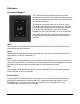
Attach the wires in the cable coming from the thermostat to the terminals on the LEFT
side of the control module into the connector labeled "Thermostat". Be sure to match
the wire color and terminal designation as identified in Step 1.
Attach the wires in the cable coming from the furnace to the terminals on the RIGHT
side of the control module labeled "Furnace/AC". Be sure to match the wire color and
terminal designation as identified in Step 1.
NOTE: If your system uses separate Rh and Rc wires, be sure to remove the jumper
wire between the Rh and Rc terminals. If your system uses a single Red wire, make
sure the jumper wire between terminals Rh and Rc is installed.
7
!