Dear Friend, Thank you for selecting Bazooka® subwoofer speaker systems for your car stereo system. Today, the Bazooka represents Bazooka Mobile Audio's continued commitment to efficiency and design. An innovative manufacturing process developed by SAS for the Bazooka provides consumers with state-of-the-art speaker system design.
CONTENTS HELPFUL HINTS BEFORE YOU BEGIN PG3 VEHICLE PLACEMENT RECOMMENDATIONS PG4 MOUNTING THE BAZOOKA PG 5-7 WIRING DIAGRAMS PG9 SPECIFICATIONS PG10 FEATURES PG 11-12 WIRING PG 13-17 TROUBLESHOOTING PG 18-19 WARRANTY PG 20-22 HELPFUL HINTS-BEFORE YOU BEGIN Please take time to read through this manual and plan out your installation before you begin! Locate an area in the rear of the vehicle where you would like to place the Bazooka speaker systems.
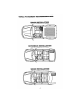
VEHICLE PLACEMENT RECOMMENDATIONS TRUCK INSTALLATION tube size is exaggerated for emphasis CI HATCHBACK INSTALLATION tube size is exaggerated for emphasis SEDAN INSTALLATION tube size is exaggerated for emphasis 4
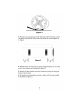
MOUNTING THE BAZOOKA Figure 1 Logo should face up 1. With the topside of the buckle facing up (see figure 1), lace the strap through the mounting base as illustrated in figure 2 ~ C Figure 2 ~:?s~ I r r I 2. After the strap is completely laced through the mounting base, make a loop with the strap, where it runs across the middle of the base as illustrated in figure 3. This loop is necessary to access the two mounting holes in the base.
Figure 4 3. Place each mounting base under the Bass Tubes® enclosure so that the apex at the bottom of the tube sits inside the mounting base as in figure 4. ~-----------------------f / \ I I I I _1- '" ! - - - - - - - - - - - - - - - - - - - - - - - - - -I,' (' I I J I \ \ \ / I \ I I I I I I I I I I I I I I I I I I I \ I I I I I I I I I J \ \ \.
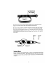
See Model Size I... For Length >1 7. Remove any slack in the strap by feeding it out of the mounting base on the loose end of the strap opposite the buckle. 8. Place the Bass Tubes® enclosure on the mounting bases and fasten the buckles as illustrated in figure 7. The strap should loop through the buckle and be tightened securely by holding the strap in place with one hand and pulling the loose end away from the buckle, but against the cabinet.
A100 WIRING DIAGRAM 16 GAUGE BLACK CHASSIS GROUND 16 GAUGE RED BATTERY (12v+) ORANGE REMOTE RCA PHONO PLUGS Right &Left Low GREEN Level Inputs HI-LEV INPUT (+) QUICK DISCONNECT YELLOW ONIOFF JUMPER LOOP NOTE: REMOVE AUTO TURN-ON LOOP TO USE ORANGE REMOTE WIRE FOR NORMAL REMOTE TURN-ON 8
A200 WIRING DIAGRAM 12BLACK GAUGE _ CHASSIS 12 GAUGE RED BATTERY YELLOW (12v+) HI-LEVEL OUTPUT (-) BROWN HI-LEVEL OUTPUT (+) GRAY HI-LEV INPUT (+) GREEN/ TRACE HI-LEV INPUT (-) 9
AMPLIFIED TUBE SPECIFICATIONS BTA10200 10/1 (SBAS 6.5" BTA8200 8/1 1" high power./high temp. 1.5/1 high power./high temp. lS high power./hlgh temp. 1/1 high power./high temp. 28 oz, 20 oz. 28 oz. 28 oz. 28 oz. 39-85 hz. 39-85 hz. 39-250 hz. 39-250 hz. 39-250 hz. sub 20-1 OOhz/Hi-pass 1DO-20khz 105 dB* 107 dB* 100 dB* 102 dB* 104 dB* 105 dB" 200 watts sub 100w xl/hi-pass 25w x4 BTA6100 6.5/1 BTA8100 8/1 BTA10100 10" Voice Coil Size 1" high power./high temp. 1/1 high power.
-;;, ........
-=: 0 0 CD m I r "" > ClI "'>" «:» C"4 C"4 :! m 00 .... m m -- X X X X X X X X X X X X X X "I X i 0 e X X X X X X X X X X ~ e X X X X X X X X X X X ~ 0 CD .... X X X X X X X X X X X ..., > ClI 0 X X X X X X X X e 0 N m m :! a:t - X X X X X X X X X X X X X X X X X X X X X X X X X X X X X X X X X X X X X X X X X X X X X X X X X X X X -....
AMPLIFIED MODELS: (BTA6100, BTAB1DO, STA10100, BTA6200, STAB20D, BTA10100) DO NOT substitute the fuse included with the Amplified Bazooka subwoofer with anything other than the SAME fast blow current rated fuse. Substitution or deletion will void the product's warranty and may cause damage to your car or the amplifier. SHOULD I USE HIGH OR LOW LEVEL INPUTS? If the source unit has only speaker outputs, use the high-level inputs of the Amplified Bazooka subwoofer.
level inputs DO NOT make any connections to the Green and Gray high-level input wires of the Amplified Bazooka subwoofer and make sure these wires are insulated to avoid the possibility of a short circuit. POWER WIRE (All Models) The power wire must be fused and connected directly to the positive terminal of the battery to provide a power source with a low voltage drop and low noise. Do not make the power connection at the fuse block or any point other than the battery.
- any of which will supply 12 Volts positive when the source is turned on. When you are using this option with: ALL A100: The Quick Disconnect YELLOW On/Off Jumper Loop MUST be disconnected from the wiring harness. ALL A200: The Aut%ff Jumper Clip must be in the off position (the two right most pins) and the Orange wire will supply turn on voltage to the Amplified Bazooka.
ADJUSTINC THE CROSSOVER A200 ONLY The built-in crossover on the Amplified Bazooka subwoofer is an 18 dB per octave electronic low pass filter. it has a 60 Hz to 250 Hz variable crossover point. Select the crossover point that you feel best fits your system design. Set the potentiometer labeled XOVER to the point you selected, 60 Hz being all the way to the left (counterclockwise) and 250 Hz being all the way to the right (clockwise). When you have set the crossover, proceed to the next step.
All A200 MODE LS Remo te Bass Contr ol and Cross over (RBCM-RS): changi ng If you find you like to vary the crossover point in additio n to want an and to g listenin are you what the level of bass depen ding on Remote al option an se purcha can you e, easy way to make this possibl Level and Crossover Contro l. your These Remot e Contro ls are accessories that are availab le from other out check to sure Be a.
TROUBLESHOOTINC Am I In Phase? If your inputs are out of phase and you turn the balance control of your radio all the way to one side, right or left the bass output from the Bazooka® will increase. When you bring the balance control back to the center position the bass level will drop. This confirms that one of your input channels is wired out of phase with the other.
PHASE CORRECTING PROCEDURE Disconnect all but one Bazooka® from your system. Be sure that any loose wire connections are insulated to avoid the chance of short-circuiting any of the electronic equipment. Listen to the system and take note of the level of the Bass Response. Connect the next Bazooka® and compare the level of the combined output to that of the single unit. If the Bass Response increases, the Phasing is correct and you can repeat this process on the next Bazooka.
LIMITED WARRANTY (UNITED STATES) Southern Audio Services, Inc., warrants all products to be free from defects in material and workmanship for a period of one (1) year from the date of purchase. In the event the product is not as warranted, SAS' sole obligation shall be to repair or replace the defective product at SAS' option: SAS limits its obligation under any implied warranties under state laws to a period not to exceed the limited warranty period.
IN MEXICO: COIBA IMPORT S.A. DE C.V . Torreci lias # 2060 Guadalajara Jalisco Col. EI Rosario Mexico C.P. 44890 Modelo: BT6014/6018, BT8014/8018, BT1014/1018, BTA6100, BTA8100, BTA10100,BT6024DVC,BT8024DVC,BT1024DVC,BTA6200,BTA8200,BTA10200 RFC CIM-000901-1kO Producto: Bocinas POllZA DE GARANTIA CONDICIONES EI producto que usted ha adquirido Cuenta con una garantla de 90 dfas Por defectos de fabricaci6n y 90 dias Deservicio a partir de la fecha de Adquisici6n otorgada por: COIBA IMPORT S.A. DE C.V 1.
N N PLEASE RETURN THIS PORTION IMMEDIATELY MODEL# PURCHASERS NAME SERIAL# STREET ADDRESS PURCHASE DATE CITY DEALER PURCHASED FROM STATE DEALER ADDRESS TELEPHONE TELEPHONE E-MAIL ZIP
PLACE STAMP HERE ~RZOOKR ~ SOUTHERN AUDIO SERVICES, INC. 15049 FLORIDA BLVD.