
Datasheet
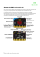
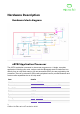
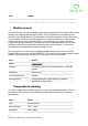
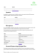
Table Of Contents

Buttons
The two buttons on the front of the micro:bit, and the 1 button on the back, are tact
momentary push-to-make buttons. The back button is connected to the KL27 interface
processor and to the NRF52 processor for system reset purposes. This means that the
application will reset regardless of if it is powered from USB or from battery.!
Front buttons A and B can be programmed in the user application for any purpose. A and
B are debounced by software, which also includes short press, long press, and ‘both
A+B’ press detection. Buttons operate in a typical inverted electrical mode, where a
pullup resistor ensures a logical ‘1’ when the button is released, and a logical ‘0’ when the
button is pressed. Both A and B buttons are connected to GPIO pins that are also
accessible on the micro:bit edge connector.!
Display
The display is a 5x5 array of LEDs. It is connected to the micro:bit as a 5x5 matrix.
Runtime software repeatedly refreshes this matrix at a high speed, such that it is within
the user persistence of vision range, and no flicker is detected. This LED matrix is also
used to sense ambient light, by repeatedly switching some of the LED drive pins into
inputs and sampling the voltage decay time, which is roughly proportional to ambient light
levels.!
Tx power
Eight user configurable settings from 0(-30dbm) to 7
(+4dbm)
Payload size
32 (standard) 255 (if reconfigured)
More Info
Micro:bit Radio
item
details
item
details
Type
2 tactile user buttons, 1 tactile system button
Debounce
(A & B) software debounced, 54ms period
Pullup
(A & B) external 4K7, (System) 10K
item
details
Type
miniature surface mount red LED
Physical structure
5x5 matrix
Electrical structure
5x5
Intensity control
Software controlled up to 255 steps
5
© Micro:bit Educational Foundation 2020