
Datasheet
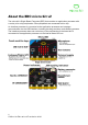
Table Of Contents

extra circuits can be re-allocated to general purpose use if some software features are
turned off.!
Power supply
Power to the micro:bit may be provided via 5V on the USB connector, or via a 3V battery
plugged into the JST connector. It is also possible (with care) to power the micro:bit from
the 3V /GND rings on the edge connector. The 3V /GND rings at the bottom can be used
to supply power to external circuits. The board uses an LDO specified up to 300mA, with
thermal cut-out for short circuit protection. !
item
details
Rings
3 large IO rings and two large power rings, 4mm plug and crocodile
clip compatible
GPIO features
19 assignable GPIO pins
$
2 are dedicated to the external I2C interface
$
6 are used for display or light sensing feature
$
2 are used for on board button detection
$
1 is reserved for an accessibility interface
$
19 may be assigned as digital input or digital output
$
19 may be assigned for up to 3 simultaneous PWM channels
$
19 may be assigned for 1 serial transmit and 1 serial receive channel
$
6 may be assigned as analog input pins
$
3 may be assigned to an optional SPI communications interface
$
3 may be assigned for up to 3 simultaneous touch sensing inputs
ADC resolution
10 bit (0..1023)
Edge
Connector
Edge connector
Pitch
1.27mm, 80 way double sided.
Pads
5 pads, with 4mm holes
item
details
Operating range
1.8V .. 3.6V
Operating current (USB and
battery)
300mA max
8
© Micro:bit Educational Foundation 2020