OWNERS MANUAL ¡
SAFETY RELATED SYMBOLS protective grounding wire or disconnect the wiring of protective grounding terminal. # ! 5 4 )/ . 2) 3+ / & %, %# 42 )# 3( /# + $/ ./ 4 /0 %. • Operating Conditions This apparatus shall not be exposed to dripping or splashing and that no objects filled with liquids, such as vases, shall be placed on this apparatus. The symbol is used to indicate that some hazardous live terminals are involved within this apparatus, even under the normal operating conditions.
CONTENTS MAXCOM SPECIFICATIONS… ………………………………………………………………………… iii AUDIO INPUT… …………………………………………………………………………………………… iii INTRODUCTION…………………………………………………………………………………………… 1 FEATURE LIST………………………………………………………………………………………………………………… 1 THE DESIGN CONCEPT … ……………………………………………………………………………… 2 THE VCA… …………………………………………………………………………………………………………………… 2 inputs… ……………………………………………………………………………………………………………………… 2 INSTALLATION……………………………………………………………………………………………… 3 UNBALANCED/BALANCED OPERATION… ……………………………………………………………………………… 4 MAI
SPECIFICATIONS MAXCOM SPECIFICATIONS AUDIO INPUT Type… ………………………………Active balanced XLR and 1/4” jack Impedance……………………………60k ohm balanced Maximum input level… ……………+21 dBu balanced and unbalanced AUDIO OUTPUT Type… ………………………………XLR and 1/4” jack Impedance……………………………1K ohm unbalanced Maximum output level………………+21 dBu Frequency response … ……………20Hz to 20KHz THD N% @ 1kHz, 4dBu……………0.05% IMD (SMPTE) @ 10dBu……………0.
INTRODUCTION INTRODUCTION Congratulations and thank you for your purchase of the BBE MAXCOM. You have acquired an extremely efficient and universal dynamics processor. It’s unique circuit design makes MAXCOM the ultimate dynamics processor: intelligent program recognition, interactive expander/gate and a fourth generation BBE® Sonic Maximizer™. FEATURE LIST • SONIC MAXIMIZER Loudspeakers have difficulty working with the electronic signals supplied by an amplifier.
DESIGN CONCEPT THE DESIGN CONCEPT THE VCA At the heart of the MAXCOM lies an industry standard state-of-the-art VCA (Voltage Controlled Amplifier). With its excellent specifications (noise, THD, control feedthrough, linearity, slew rate and temperature stability) the precision VCA used in the MAXCOM is considered one of the best in VCA technology. The “control feedthrough” used in VCA terminology is a very critical parameter for the crosstalk of the control voltage into the audio path.
INSTALLATION INSTALLATION Your MAXCOM was carefully packed at the factory and the packaging was designed to protect the unit from rough handling. Nevertheless, we recommend that you carefully examine the packaging and its contents for any signs of physical damage which may have occurred in transit. If the unit is damaged please do not return it to us but notify your dealer and the shipping company immediately, otherwise claims for damage or replacement may not be granted.
INSTALLATION • IMPEDANCE The input has an impedance of 60k Ohms and can be driven by most input sources. UNBALANCED/BALANCED OPERATION 90% of all mistakes in audio installations can be attributed to incorrect and defective audio connections! In order to utilize the MAXCOM to its full potential, please pay special attention to the following section.
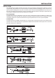
FRONT PANEL CONTROLS CONTROLS FRONT PANEL LAYOUT OF THE MAXCOM -14 N 14 -30 2.5 -10 -15 -50 -70 0 -20 -30 0 50 2 5 10 8 1 10 1.5 0.5 100 0 1 0.3 0.1 150 2 N 6 -6 -14 N N N N N 2 N 0.1 150 6 -6 N 1 1 0.3 #( N 14 N 8 10 1.5 100 N N 10 N N N -30 5 0 N 0 2 0.5 N -70 0 -20 50 N -15 -50 #( 2.5 -10 N 1 N lim 2!4)/ 0.1 MS 200 4 SEC 2%,%!3% -20 D" 20 3 4 5 9 7 8 ).
FRONT PANEL CONTROLS 13. GAIN REDUCTION meter The GAIN REDUCTION meter indicates the actual gain reduction and displays this in a range of 0dB to infinity. 14. LINK SWITCH Engages the LINK function. 15.
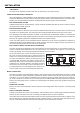
REAR PANEL REAR PANEL THE BACK PANEL LAYOUT OF THE MAXCOM 1 2 3 4 5 3 4 5 1. AC JACK & AC FUSE HOLDER Please note that, depending on the main voltage supplied to the unit, the correct fuse type and rating must be installed. 2. AC voltage selector: This selector allows choosing the supply voltage for the MAXCOM from either 115Vac or 230Vac. The supply voltage can only be selected by a SERVICE CENTER. 3.
OPERATION OPERATION EXPANDER/GATE SECTION A downward expander automatically reduces the overall level for all signals below the threshold. The expander therefore operates in the opposite way to that of a compressor/limiter. Expanders generally function with a flat ratio curve in that the signal continually fades. Noise gates, however, can be seen as “high ratio” expanders. If the signal falls below he threshold it is radically attenuated.
operation A ratio of 1:1 indicates that the output signal will correspond to the input signal i.e., there is no level change. A ratio of 2:1 indicates that for every 2 dB increase in input level above the threshold there will be a corresponding increase in output level of 1dB. A ratio of 10:1 indicates that for every 10dB increase in input level above the threshold there will be a corresponding increase in output level of 1dB, etc.
OPERATION BBE SECTION In order to address problems inherent in basic loudspeaker design, BBE Sound, Inc. has developed a circuit that has two primary functions. The first adjusts the phase relationship of the low, mid and high frequencies. Since a loudspeaker¹s natural tendency is to add progressively longer delay times to higher frequencies, the BBE circuit adds progressively longer delay times to lower frequencies.
APPLICATIONS APPLICATIONS In this section several typical applications of the MAXCOM are discussed. The following basic settings can resolve most dynamic problems. They are the ideal starting point. Please take the time to study the application examples carefully to make full use of the MAXCOMs capabilities in the future.
APPLICATIONS during recording or playback. They are usually used when recording drum kits, where the mics are very close to each other. High volume levels of individual instruments often cause considerable leakage onto all the adjacent mics and results in conflicting frequency and phase coherence problems, as well as unspecified sounds (“comb” filter effects). It is vitally important that every instrument is recorded into a separate mic and that each mic is individually gated.
APPLICATIONS pleasant feedback problems. If the MAXCOM is inserted into the mic channel, it will shut off the channel when it is not being used reducing the possibility of feedback. • Noise Reduction On Effects Paths The effects rack is one of the most overlooked sources of noise in a PA system or recording facility.
applications as a creative tool, laying the groundwork for many of the sounds which are now considered indispensable in contemporary music. The compressor is used in this role because you can hear it working, and control of the dynamic range is of secondary importance. The MAXCOM, with its extensive range of functions, is well suited to this application. Sound effects of this kind can be achieved using “extreme” settings.
SPECIAL applications SPECIAL APPLICATIONS • USING THE MAXCOM FOR RECORDING 1. The MAXCOM In Digital Recording And Sampling In an analog recording low recording levels lead to an increased noise level, whereas high levels will cause a compressed and “squashed” sound. In contrast to analog, side effects in digital always become extremely audible: with decreasing level, a recording with insufficient level loses resolution: the recording sounds “hard” and loses “atmosphere”.
SPECIAL applications The MAXCOM in a two way system EXTERNAL SIDECHAIN APPLICATIONS • THE SIDECHAIN CONNECTOR The MAXCOM offers an exceptionally versatile external facility by using the SIDECHAIN connector. By using this external control input, the MAXCOM control path is disconnected from the audio input and therefore interrupted (see “BLOCK DIAGRAM”).
special applications • Initial Settings for the De-Esser Functions CONTROL SETTINGS EXP. THRESHOLD control… …… OFF THRESHOLD control……………+20 dB RATIO control……………………… LIM ATTACK control……………… 0.1 msec AUTO switch… …………………… OUT OUTPUT CONTROL……………… 0 dB PROCESS control…………………… IN 1 - Turn the THRESHOLD control counterclockwise until the GAIN REDUCTION meter shows an appropriate drop in level.
special applications equalizing process, feedback remains a difficult problem. Often enough, acoustic changes occur as the audience enters the room, which again leads to feedback problems. In addition, the frequency response of the whole system is modified and thus affected by equalizer operation. Dynamic feedback control is a better solution. Similar to the previously mentioned de-esser application, an equalizer is not inserted into the audio path but into the sidechain path of the MAXCOM.
SERVICE/WARRANTY/MAINTENANCE Service We recommend that if at all possible, a BBE MAXCOM which requires service be sent to our facility in Huntington Beach, California. We request that a “RETURN AUTHORIZATION” be issued by the dealer from whom you purchased the unit. If this is not possible, call BBE Sound, Inc. directly at (714) 897-6766, extension 116 to obtain a “RETURN AUTHORIZATION”. Include a copy of the bill of sale with the unit when it is shipped to BBE Sound, Inc.
¡ 5381 Production Drive Huntington Beach, CA 92649 714-897-6766 • FAX 714-896-0736 www.bbesound.com covered by U.S. Patent 5,736,897 and other U.S. and foreign patents pending. BBE is the registered trademark of BBE Sound, Inc.