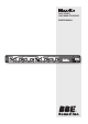
2 WAY STEREO 3 WAY MONO CROSSOVER OWNERS MANUAL ¡
SAFETY RELATED SYMBOLS protective grounding wire or disconnect the wiring of protective grounding terminal. # ! 5 4 )/ . 2) 3+ / & %, %# 42 )# 3( /# + $/ ./ 4 /0 %. • Operating Conditions The symbol is used to indicate that some hazardous live terminals are involved within this apparatus, even under the normal operating conditions.
CONTENTS SPECIFICATIONS… ……………………………………………………………………………………… iii Service… ………………………………………………………………………………………………… iii Warranty………………………………………………………………………………………………… iii INTRODUCTION…………………………………………………………………………………………… 1 Getting Started … …………………………………………………………………………………… 1 READ BEFORE USING …………………………………………………………………………… 1 FEATURE LIST……………………………………………………………………………………… 1 Inputs & Outputs ……………………………………………………………………………… 1 SONIC MAXIMIZER……………………………………………………………………………… 1 Clip LED …………………………………………………………………………………………… 2 Ra
SPECIFICATIONS SPECIFICATIONS CROSSOVER TYPE… ……………………………………………………………………… Mono 3 way/Stereo 2 way FILTER TYPE… ……………………………………………………………………………… Linkwitz/Riley 24dB/octave CROSSOVER FREQUENCY Max-X3 LOW-MID Range 1 … ……………………………………………………………………………………… 80Hz-1KHz MID-HIGH Range 10 … …………………………………………………………………………………800Hz-10KHz INPUTS: TYPE… ……………………………………………………………… Balanced XLR and Unbalanced 1/4” IMPEDANCE……………………………………………………………………………………… 100KOhms OUTPUTS: TYPE… ……………………………………………………………… Balanced XLR and U
Getting started INTRODUCTION Congratulations and thank you for your purchase of the BBE Max-X3. You have acquired an extremely efficient and universal stereo crossover with an integral BBE® Sonic Maximizer™. Getting Started READ BEFORE USING Before starting to use the crossover in your sound system there is some information you should know and procedures you should follow. The Max-X3 is a fourth order Linkwitz-Riley electronic crossover.
INTRODUCTION This change in the phase and amplitude relationship on the harmonic and fundamental frequencies is technically called “envelope distortion.” The listener perceives this loss of sound integrity in the reproduced sound as “muddy” and “smeared.” In the extreme, it can become difficult to tell the difference between musical instruments, for example, an oboe and a clarinet. BBE Sound, Inc. conducted extensive studies of numerous speaker systems over a ten year period.
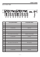
front panel Max-X3 FRONT Panel 1 12 2 4 3 6 5 8 7 10 9 13 11 15 14 17 16 19 18 21 20 22 23 2-way Stereo Mode 3-way Mono Mode 1 Ch1 BBE Process Control BBE Process Control 2 Ch1 BBE Lo Contour Control BBE Lo Contour Control 3 Ch1 BBE switch BBE switch 4 Ch1 Input Level Input Level 5 Ch1 LOW & Ch1 HIGH Clip LEDs Low & Mid Clip LEDs 6 Ch1 LOW Gain LOW Gain 7 Ch1 LOW Mute LOW Mute 8 Ch1 LOW-HIGH Crossover Frequency LOW-MID Crossover Frequency 9 Ch1 LOW-HIGH Crossover Ra
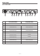
rear panel Max-X3 Rear Panel 2W-STEREO HIGH OUT 2 LOW OUT 2 BALANCED BALANCED 95-120V /210-240V 60-50Hz Rated power consumption 10w HIGH PHASE FUSE 210-240V T100mAL 250VAC 95-120V 200mA 250VAC Replace fuse with correct type only MADE IN CHINA C STEREO MONO BALANCED HIGH OUT 1 BALANCED UNBALANCED CD BOOST MODE CHANNEL 1 IN LOW OUT 1 BALANCED UNBALANCED BALANCED UNBALANCED HIGH PHASE UNBALANCED CD BOOST US 3W-MONO HIGH OUT MONO MID OUT MONO MONO INPUT LOW OUT MONO 1 2 CHANNEL 2
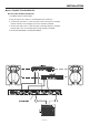
INSTALLATION Max-X3 Connection Examples Max-X3 2-way stereo operation 1. Set Mode switch to stereo Mode. 2. Plug the Left line-in to INPUT 1 and the Right line-in to INPUT 2. 3. Connect the LOW OUT 1 to the Left input of the Low frequency amplifier, and the LOW OUT 2 to the Right input of Low frequency amplifier. 4. Connect the HIGH OUT 1 to the Left input of the High frequency amplifier, and the HIGH OUT 2 to the Right input of High frequency amplifier. 5. Set the XOVER FREQ 1 and XOVER FREQ 2.
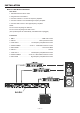
INSTALLATION Max-X3 3-way mono operation Rear Panel 1. Set Mode switch to Mono mode. 2. Plug the line-in into INPUT 1. 3. Connect LOW OUT 1 to the Low frequency amplifier. 4. Connect LOW OUT 2 to the Midrange frequency amplifier. 5. Connect HIGH OUT 2 to the High frequency amplifier. NOTE: Do not connect anything into INPUT 2. Do not connect anything from HIGH OUT 1. (The inputs/outputs are automatically normalled when unplugged). Front Panel 1. BBE 1… …………………………………………………… BBE main control 2.
installation Connection cables In this chapter you’ll find the wiring diagrams for the connectors to be used with your crossover. Take care of the connector cable. Always holding them by the connectors and avoiding knots and twists when coiling them: this gives the advantage of increasing their life and reliability, which is always to your advantage .
¡ 5381 Production Drive Huntington Beach, CA 92649 714-897-6766 • FAX 714-896-0736 www.bbesound.com covered by U.S. Patent 5,736,897 and other U.S. and foreign patents pending. BBE is the registered trademark of BBE Sound, Inc. rev 3: 9.08.