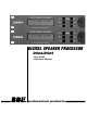
DIGITAL SPEAKER PROCESSOR DS24/DS26 •User Guide •Reference Manual professional products
® i IMPORTANT SAFEGUARDS
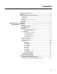
CONTENTS Jump ahead to quick start DS24/DS26 and DS26 Features ……………………………………………………v 1 Introduction ……………………………………………………………………vi 2 What is a Speaker Management System? ……………………………………1 2.1 Crossover: ……………………………………………………………………1 2.2 Equalization: …………………………………………………………………1 2.3 Delay: ………………………………………………………………………1 2.4 High Pass and Low Pass Filters: …………………………………………1 2.
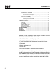
CONTENTS ® 8.3 STARTING UP SYSOMAX ………………………………………………18 8.3.1 From the Start menu: ……………………………………………18 8.3.2 From Windows Explorer or My Computer: ……………………18 8.4 Navigating SYSOMAX ……………………………………………………18 8.4.1 Crossover Types DS24 …………………………………………19 8.4.2 Crossover Types DS26 …………………………………………19 8.4.3 Top Line Menu ……………………………………………………20 9 Creating a Program ………………………………………………………………22 9.1 GAINS: ……………………………………………………………………22 9.2 DELAYS: ……………………………………………………………………22 9.
DS24/DS26 AND DS26 FEATURES Crossovers • Choice of 2 X2-way, 2 X 3-way, 2-way + sub, 4-way, 5-way 6-way crossover (depending on model) Parametric Equalizers • DS24 is 2 inputs 4 outputs and includes 4 crossover configurations • DS26 is 2 inputs 6 outputs and includes 6 crossover configurations Driver Alignment Delay Speaker Protection limiter 10 user memories • Input gain control for each channel • Separate crossover controller • 5 band fully parametric equalizer • Driver Alignment Delay for each outp
® INTRODUCTION Thank you for choosing the BBE DS24/DS26 Speaker Management System. This product will enable you to obtain the best possible performance from your loudspeaker system. You can also reduce the amount of outboard gear that is required to transport, set-up and operate as part of the sound system. The DS24/DS26 offers many powerful functions. It is highly recommended that you read through this manual before you begin connection and operation.
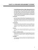
WHAT IS A SPEAKER MANAGEMENT SYSTEM? A Speaker Management System uses digital signal processing to accomplish multiple functions that affect the audio signal between the mixer and the power amplifiers. These functions include crossover, equalization, delay, limiting, high-pass and low-pass filtering as well as signal distribution. Programs may be created, selected and edited with the DS24/DS26's front panel controls.
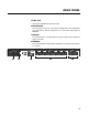
FRONT PANEL ® 1. LCD The 2x20 backlit LCD displays the program and programming choices of the unit. 2. These buttons allow navigation for selection of sub-menus and some parameter values. 3. Menu This is one of two buttons that will access the front panel programming. This one is used primarily to select which program to call up, edit or save. 4. Gain This is one of two buttons that will access the front panel programming.
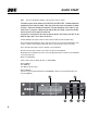
REAR PANEL 1. Power Jack This accepts a standard IEC type AC bayonet plug. 2. RS232 Interface Connect this to the serial port on a PC using the included cable or other standard DB-9 type cable. With the software installed, the PC can now monitor and program the DS24/DS26. 3. XLR Input These are balanced (Pin 2 Hot) XLR inputs that accept the signal from the (usually main) outputs of the mixer. 4. XLR Output These are balanced (Pin 2 Hot) XLR outputs.
QUICK START ® NOTE: This section will describe navigation of the front panel controls as follows: The button to press will be shown in ALL CAPITALS. For QUICK START, a number following in parentheses (#) will also be included. These refer to the same names and numbers as shown in Figure 1, Front Panel Controls and Indicators. The expected display text is shown in "quotation marks".
QUICK START Depending on the mode selected, other options will appear for this level of the menu, primarily concerned with input and output assignments. Some assignments are fixed with the crossover type selected. Only those assignments that can be selected will show on the display. Either the BACK/NEXT (2) buttons or the Parameter dial will work for stepping through the selections. 10. Press GAIN (4). Set the gain for Input: A. Press NEXT (2) and set the gain for Input B.
INSTALLATION ® Your DS24/DS26 was carefully packed at the factory and the packaging was designed to protect the unit from rough handling. Nevertheless, we recommend that you carefully examine the packaging and its contents for any signs of physical damage that may have occurred in transit. If the unit is damaged please do not return it to us but notify your dealer and the shipping company immediately, otherwise claims for damage or replacement may not be granted.
OPERATION There are two methods of creating and selecting programs on the DS24/DS26. 1.The first method uses the front panel controls of the unit and requires stepping through menus to access the proper parameter that needs adjusting. Once programs have been saved to the onboard memory, calling up a program is quite simple. See QUICK START on page XX for an example of navigating and programming a program. 2.The second method uses the included Graphical User Interface (GUI) software run on a Windows PC.
OPERATION ® you back, simply hit EXIT and start again. Where an additional "ENTER" press is required to write the selection to memory, the screen will prompt you with "[ENTER] to Confirm". The LED display also offers some hints. Left or right arrows on the top line indicate the BACK/NEXT buttons will step to other choices. 7.2 SUBMENUS 7.2.1.1 Crossover Submenu This menu selects the type of crossover and is the primary submenu to create, recall, delete, and name a program configuration.
OPERATION Press MENU, NEXT and ENTER. Then use the NEXT/BACK and ENTER buttons to adjust the Security Submenu. The various locking modes are as follows: 1.LOCK: Changes only: Parameters can be viewed, but cannot be adjusted. MUTE buttons are valid. 2.LOCK: Changes + View: Parameters cannot be viewed or adjusted. MUTE buttons are valid. 3.LOCK: Changes + Mutes: Parameters can be viewed, but cannot be adjusted. MUTE buttons are not valid. 4.LOCK: Everything: Parameters cannot be viewed or adjusted.
OPERATION ® A.Determines whether the outputs will stay muted on power up until manually switched off (Mute Hold) or the level will gradually fade up to the operating level (Fade In). The fade-in time is fixed. B.Fade-in: Mutes are off, but Output channels rise to programmed levels gradually. C.Mute Hold: All Output channels are muted until the mutes are manually disabled either on the front panel or through the GUI. 3.
OPERATION 7.6.1.2 Outputs: Press NEXT again and the screen will display an Output (Op1 = Output 1). Set the desired input gain level. At this point you can use the BACK/NEXT buttons to step through each of the parameters for the currently selected output. Press the GAIN button again to go to the next Output and program all of its parameters. (The GAIN button will now select only the Output channels; the gain adjustment screens for the Inputs will not be displayed unless you exit the menu and start again.
OPERATION ® HiPass: frequency range 10Hz~16.0KHz LoPass: frequency range 35Hz~22.0KHz Use HPF and LPF together to define the frequency band for this channel of the crossover. 7.6.1.7 PEQ: ✧ } { = Set the parameters for the five available bands of parametric EQ. Press the PARAM dial to toggle between the three parameters on the display. These include Frequency, Q and Cut or Boost. Pressing the ENTER button in this mode will select the symbol in the upper right corner.
OPERATION gain to the program level after the threshold point has been exceeded by the incoming signal. Generally, set shorter attack times on outputs that are feeding mids and highs and longer attack times for lows and subs. The time should be chosen carefully as the danger of dynamics distortion usually increases with shorter attack times. The attack time of the DS24/DS26 can be set within a range of 1 to 100 milliseconds. 3.
BLOCK DIAGRAMS ® 7.
BLOCK DIAGRAMS GAIN INPUT A SUM A+B GAIN INPUT B OUT 5 & 6: B OUT 5 & 6: A+B HPF LPF PEQS Delay GAIN MUTE MUTE LOW OUTPUT 1 HPF LPF PEQS Delay GAIN MUTE MUTE HIGH OUTPUT 2 HPF LPF PEQS Delay GAIN MUTE MUTE LOW OUTPUT 3 HPF LPF PEQS Delay GAIN MUTE MUTE HIGH OUTPUT 4 HPF LPF PEQS Delay GAIN MUTE MUTE MSUB OUTPUT 5 HPF LPF PEQS Delay GAIN MUTE MUTE AUX OUTPUT 6 HPF LPF PEQS Delay GAIN MUTE MUTE LOW OUTPUT 1 HPF LPF PEQS Delay GAIN MUTE MUTE
BLOCK DIAGRAMS ® 7.
GRAPHICAL USER INTERFACE (GUI) The BBE SYSOMAX software provides a graphical method of programming on a DS24 or DS26. It can also be used to make changes in real time, if adjustments are required, during live operation. Full metering and control of all settings available on the PC. Because it provides a more graphic and overall view, this method will allow you to program settings more efficiently than using the front panel navigation method on the DS24/DS26.
® GRAPHICAL USER INTERFACE (GUI) 2.Select My Computer from the Desktop or Start menu. 3.Click on BBE (D) (CD-ROM drive is usually drive D) 4.Double click on the file that then displays: DS26_ds24Setup_v13.exe 5.The Setup Wizard screen will appear. 6.Follow the prompts displayed on the screen to install the program. 7.When the installation is complete, eject the CD-ROM 8.3 STARTING UP SYSOMAX To create a preset program on a DS24 or DS26 unit , first connect it to the computer with the serial cable.
GRAPHICAL USER INTERFACE (GUI) 2.Click NEW. A dialog box labeled “Unit” will appear in the screen. 3.Device ID assigns a number between 1 and 64 to the unit. 4.Select Unit Type selects whether the unit is a DS24 or a DS26. 5.Format selects the main crossover mode for the unit. There are four types available for the DS24 and six types available for the DS26. The next frame assigns certain input and output options and is device and mode dependent: 8.4.
® GRAPHICAL USER INTERFACE (GUI) You should now see the global view. This is the main screen from which to make your programming choices. 8.4.3 Top Line Menu 1.File gives the typical Windows file management choices. 2.Config provides two choices: Modify and RS-232. Clicking Modify will open the Unit dialog box. Clicking RS-232 lets you assign the Com port and baud rate for your particular computer. 3.Status activates/deactivates the connection between the computer and the unit.
GRAPHICAL USER INTERFACE (GUI) desired and click OK. The dialog box will close and you will be returned to the main screen view. To rename a program that has already been named, click on a program location in the table, then click Rename. Enter the desired name in the text box and click OK. The dialog box will close and you will be returned to the main screen view. Recall downloads the current version of the selected program from the computer to the device. Erase will immediately erase a selected program.
CREATING A PROGRAM ® Once the device type and crossover type have been selected, the main screen will show blocks for each programmable section. The term “program” as used here is equivalent to “preset” as used on other programmable devices. When entering values into text boxes you can use your pointing device such as a mouse or touchpad. You can also use the up/down/left/right cursor arrows for certain functions such as Gain sliders and up/down incremental value arrows. 9.
CREATING A PROGRAM 9.4 OUT 1, OUT 2, etc. Each tab selects an output channel. Use this screen to program crossover frequencies, filter type, and up to five parametric EQ’s. In addition, the same programming choices as on the GAIN screen are duplicated here, but just for the selected output channel. 9.5 Crossover Filters: [insert screen shot of PEQ filet settings screen] The Low and High frequencies set the frequency bandwidth for the selected channel of the crossover.
® CREATING A PROGRAM Use the sliders to select values for Frequency., Q and Gain (cut/boost). An additional check box for FLAT will bypass all value selections. At the bottom of the screen are forward and back arrows to step through the five PEQ’s. Gain must be set to 0 (zero) to select a different type of filter including the Hi or Low Shelf filter. Gain must remain at 0 for the shelving filters. Click the Set 0dB button to move the Gain slider to 0 dB or move the slider.
SPECIFICATIONS BALANCED INPUTS As standard, the DS24/DS26 comes with electronically servo-balanced inputs. This circuit design features automatic hum and noise reduction for balanced signals and thus allows for trouble-free operation even at high operating levels. Externally induced mains hum etc. will be effectively suppressed.
® SERVICE • WARRANTY • MAINTENANCE 11 SERVICE We recommend that if at all possible, a BBE DS24 or DS26 that requires service be sent to our facility in Huntington Beach, California. We request that a “RETURN AUTHORIZATION” be issued by the dealer from whom you purchased the unit. If this is not possible, call BBE Sound, Inc. directly at (714) 897-6766, extension 116 to obtain a “RETURN AUTHORIZATION”. Include a copy of the bill of sale with the unit when it is shipped to BBE Sound, Inc.
SERVICE • WARRANTY • MAINTENANCE is not within the warranty period. All non-warranty repairs are warranted for a period of 90 days from the date of service. BBE Sound, Inc. is NOT LIABLE FOR CONSEQUENTIAL DAMAGES. Should the unit fail to operate for any reason, our sole obligation is to repair it as described above. DO NOT RETURN ANY PRODUCT TO THE ABOVE ADDRESS WITHOUT INSTRUCTIONS AND AUTHORIZATION ISSUED BY THE ABOVE LOCATION.
® 5381 Production Drive Huntington Beach, CA 92649 714-897-6766 • FAX 714-896-0736 www.bbesound.com BBE is the registered trademark of BBE Sound, Inc. rev.