882 SONIC MAXIMIZER User Guide and Reference Manual
i
TABLE OF CONTENTS Important Safeguards ……………………………………………………………………………………………………………i BBE Process Explained ……………………………………………………………………………………………………………1 Product Description ………………………………………………………………………………………………………………2 Applications ………………………………………………………………………………………………………………………2 Front Panel Controls ……………………………………………………………………………………………………………3 Rear Panel Connections …………………………………………………………………………………………………………4 Specifications ………………………………………………………………………………………………………………………5 General Operation ……………………………………………………………………………………
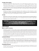
Product Description The BBE 882 is a dual channel, single rack space device for use in +4dBu balanced line applications. Each of the two independent channels has a Lo Contour control, Process control and a 5 segment LED input level meter. A single function button switches the BBE process on or off in both channels, which is useful for comparing the processed sound to the unprocessed sound. An LED next to the function button glows green when the BBE process is on and red when the process is off.
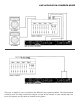
FRONT PANEL CONTROLS 1 SONIC MAXIMIZER 3 4 5 6 POWER BBE PROCESS ® CLIP +10 0 - 10 IN - 20 OUT - 20 - 10 0 +10 CLIP ▼ ▼ 882 2 ON CHANNEL A LO CONTOUR PROCESS FUNCTION LO CONTOUR PROCESS OFF CHANNEL B 1. LED DISPLAY: The LED display is used to indicate the output signal level of the BBE 882. Each number on the front panel corresponds to the output signal level, measured in decibels. Example: The “+10” indicates a 10dBu signal level, “0” refers to 0dBu, and so on.
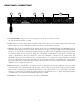
REAR PANEL CONNECTIONS 1 2 3 4 5 1. AC POWER CORD: Plugs into AC power receptacle. U.S. Model, 100-120Vac, 50/60Hz. All other models,220-240Vac, 50/60Hz. 2. FUSE: Turn cap on fuse holder counter-clockwise to remove fuse. (Note: For U.S. Model, replace with 250Vac, 1/2A Fastblow type fuse. For all other models, replace with 250Vac, .125A Fastblow type fuse.) 3. OUTPUT: The output of the BBE 882 can be taken from the 1/4” stereo TRS Phone Jack or the XLR Jack.
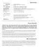
Specifications Frequency Response, process mode: ……………Program controlled bypass mode: ……………10Hz to 50kHz +/-0.5dBu, 0dBu input Signal to Noise: ……………………-92dBu THD, process mode: ……………less than 0.025% at -0dBu input, 20-20kHz bypass mode: ……………less than 0.002% at -0dBu input, 20-20kHz Maximum Output: ………………+23dBu (may vary due to control settings) Input Impedance: …………………14.7k Ohms, balanced 1/4" TRS phone jack or XLR jack Pin #2 hot or “+”.
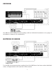
LIVE APPLICATION: NON-POWERED MIXER Connect the BBE 882 to the output of the mixing console. The output of the BBE will drive either a crossover or a power amplifier directly. (If an equalizer is being used, refer to “BBE and Equalization” section under “General Operation.
LIVE APPLICATION: POWERED MIXER There are a couple of ways to configure the BBE 882 into a powered mixer. The ideal method would be into “Pre-Amp Out/Power Amp In” section of the console. If your console does not have this option, use the main or channel insert points.
RECORDING The BBE 882 can be utilized in the recording studio on individual instruments or on groups of instruments to improve the sound quality. MASTERING OR DUBBING Use the BBE 882 for mastering the recording. Even if the BBE Process has been used on individual tracks, an improvement on the total mix will be noticed.
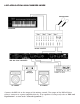
INDIVIDUAL INSTRUMENTS Use the BBE 882 in the effects loop or the main output of a guitar preamp. For keyboards, the output of the sub-mixer will be the ideal location.
SOUND CONTRACTORS The BBE 882 will accept the output level of most sound contractor type mixers.
Service We recommend that if at all possible, a BBE 882 which requires service be sent to our facility in Huntington Beach, California. We request that a “RETURN AUTHORIZATION” be issued by the dealer from whom you purchased the unit. If this is not possible, call BBE Sound, Inc. directly at (714) 897-6766, extension 116 to obtain a “RETURN AUTHORIZATION”. Include a copy of the bill of sale with the unit when it is shipped to BBE Sound, Inc. so that the service can be expedited.
Calibration Procedure for the BBE 882 (REV/S/ON 1.1) NOTE: THIS UNIT WAS TESTED AND CALIBRATED AT THE FACTORY. THIS PROCEDURE IS FOR QUALIFIED PERSONNEL ONLY. INITIAL SETTINGS: 1. BBE Process controls VR1 and VR3 to minimum.(C.C.W.) 2. Lo Contour controls VR2 and VR4 to minimum.(C.C.W.) 3. Power switch “ON” and BBE function switch “IN”. POWER SUPPLY TEST: 1. With DVM set to DC volts, measure the positive end of C37. You should read less than +30vdc. 2.
13
14
15
16
NOTES: 17
YEA Y RANT E R W IV 5 AR F BE • • B LI MITED 5381 Production Drive Huntington Beach, CA 92649 714-897-6766 • FAX 714-896-0736 www.bbesound.com covered by U.S. Patent 4,482,866 and other U.S. and foreign patents pending. BBE is the registered trademark of BBE Sound, Inc. rev.