4020 Fire Alarm System System Troubleshooting Guide 574-771 Rev. A Technical Manuals Online! - http://www.tech-man.
Copyright and Trademarks Copyright 1998 Simplex Time Recorder Co. All rights reserved. Printed in the United States of America. Information in this document is subject to change without notice. No part of this document may be reproduced or transmitted in any form or by any means, electronic or mechanical, for any purpose, without the express written consent of Simplex Time Recorder Company.
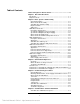
Table of Contents Tables and Figures In this Document................................................... ii Chapter 1 About This Document Introduction ....................................................................................... 1-1 Chapter Content................................................................................. 1-1 Chapter 2 Basic System / Sub-Assembly General Description........................................................................ 2-1 Master Controller Assembly .......
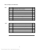
Tables and Figures in this Document Tables Figures Table Description Page Table 2-1 4020 System Device Address Assignments 2-2 Table 2-2 565-325 Master Controller PCB Assembly I/O Connectors 2-5 Table 2-3 Jumper Plug Color Code Scheme 2-7 Table 2-4 565-222 & 565-368 Standard Slave PCB Assembly I/O Connectors 2-8 Table 2-5 565-256 Power I/O Interface PCB Assembly I/O Connectors 2-11 Table 2-6 565-220 Power I/O Interface PCB Assembly I/O Connectors 2-11 Table 2-7 636-341 (Gold Wing) P
Chapter 1 About This Document Introduction This troubleshooting guide provides you with a basic understanding of the 4020 Fire Alarm Control Panel operation and suggestions for quickly finding and resolving problems.
Chapter 2 Basic System / Sub-Assembly General Description The basic 4020 Fire Alarm Control Panel is comprised of four assemblies: • Master Controller • Standard Slave (Part No. 565-325) (Part No. 565-368 for Universal Supply installation 565-222 for Intelligent Supply installation) • Power I/O Interface (Part No. 565-256 for Universal Supply installation 565-220 for Intelligent Supply installation) • Power Supply (Part No.
Basic System/Sub-Assembly, Continued Expansion The basic 4020 Fire Alarm Control Panel is capable of supporting system expansion with peripheral cards. Although not discussed further in this troubleshooting document, the following list shows some of the supported expansion cards: • • • • • • Addressing RS-232 Interface (Part No. 565-430) [supercedes 565-224] Optional Mapnet Transceiver Interface (Part No. 565-241) 8 Point I/O (Part No.565-211) Contact Closure DACT (Part No. 565-627) Serial DACT (Part No.
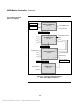
4020 Master Controller Description The Master Controller PCB assembly supervises panel operations and controls the front panel user interface. The Master Controller communicates with panel PCB subassemblies via a +28V signal level communications interface. Peripheral PCB assemblies are optically coupled to this communications interface.
4020 Master Controller, Continued System Block Diagram (Universal Supply) KEYPAD/LEDs P1 LCD DISPLAY P8 MASTER CONTROLLER (565-325) P3 TB1 TO PROGRAMMER CABLE CITY, TBL, RUI COMM P2 COMM / POWER (+28, +5, 0V) P6 P7 TB1 I/O #1 I/O #2 TB2 I/O #3 TB3 STANDARD SLAVE (565-368) TB4 I/O #4 TB5 COMM / POWER TO OPTIONS MAPNET P8 +36V, 0V P5 +5V, +28V, 0V P9 STATUS / CONTROL J1 OPTION INTERFACE TB1 A TAP TB2 B TAP TB3 C TAP TB4 P4 POWER I/O INTERFACE (565-256) P9 P2 P3 +36V TO
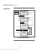
4020 Master Controller, Continued System Block Diagram (Intelligent Supply) KEYPAD/LEDs P1 LCD DISPLAY P8 MASTER CONTROLLER (565-325) P3 TO PROGRAMMER CABLE TB1 CITY, TBL, RUI COMM P2 COMM / POWER (+28, +5, 0V) P6 P7 TB1 I/O #1 I/O #2 TB2 I/O #3 TB3 STANDARD SLAVE (565-222) TB4 I/O #4 COMM / POWER TO OPTIONS TB5 MAPNET P8 +36V, 0V P5 +5V, +28V, 0V P9 STATUS / CONTROL P1 P2 POWER I/O INTERFACE (565-220) P8 P9 +36V TO OPTION BOARD TB1 A & B TAPS P7 P5 J1 SUPPLY CONTROL &
4020 Master Controller, Continued Master Controller PCB Layout P1 P2 P4 TB1 P3 P6 P5 JW2 JW1 SW1 P7 U8 CFIG (Note Orientation) Figure 2-3. 565-325 Master Controller PCB Assembly Master Controller PCB Assembly I/O Connectors Table 2-2 describes the I/O connectors on the Master Controller PCB Assembly (refer to Figure 2-2 for the location of these connectors). Table 2-2.
4020 Standard Slave Description The Standard Slave PCB assembly controls and supervises four I/O circuits, a single Mapnet channel and the Power I/O Interface assembly and has the following features: • A bi-directional 8 bit bus permits supervision and control of the Power Supply via the Power I/O Interface assembly. • The Standard Slave communicates with the Master Controller via Serial communications. This is accomplished through optically isolated transmit and receive.
4020 Standard Slave, Continued Standard Slave PCB Layout TB5 P8 P1 TB1 P2 JW1 JW2 TB2 U11 P3 SW1 TB3 P4 SW2 TB4 P9 P5 P6 P7 Figure 2-4. 565-222 & 565-368 Standard Slave PCB Assembly Standard Slave PCB Assembly I/O Connectors Table 2-4 describes the I/O connectors on the Standard Slave PCB Assembly (refer to Figure 2-4 for the location of these connectors). Table 2-4.
4020 Power I/O Interface Description The Power I/O Interface circuitry permits the Standard Slave to supervise and control the Power Supply. A bi-directional 8 bit bus provides Standard Slave access to Power I/O Interface status and control registers. The Power I/O Interface assembly converts +28.5 volt A-tap power to 36V Mapnet power. Local 28 UPS unswitched power, battery relay control and primary power supervision is provided by the P9 ribbon cable connection to the Power Supply.
4020 Power I/O Interface, Continued RED BLK YEL Power I/O Interface PCB Layout P4 J1 P5 P12 TB2 P1 P2 TB3 P10 P13 TB4 R139 P3 P14 P6 P7 P8 P9 P11 Figure 2-5. 565-256 Power I/O Interface PCB Assembly J1 J2 P3 P4 P5 P6 P7 TB1 P1 P8 P2 P9 Figure 2-6.
4020 Power I/O Interface, Continued Power I/O Interface PCB Assembly I/O Connectors Table 2-5 describes the I/O connectors on the 565-256 Power I/O Interface PCB Assembly (refer to Figure 2-5 for the location of these connectors). Table 2-5.
4020 Power Supply Description The Switcher Power Supply converts 120/220/240VAC input line voltage into 28 volt DC power. The supply provides brownout detection status to the Power I/O Interface board. A relay permits the Standard Slave to select power from either the Power Supply or battery. An over voltage protection circuit supervises the DC output to prevent system sub-assembly damage.
Chapter 3 4020 Problem Experience Overview This chapter presents 4020 problems experienced in the field and those analyzed by Service Repair. This information is arranged in three categories: • General Issues • Problems Associated with Assembly / Dis-Assembly and Installation • Problems Associated with Power Supplies Where Problems are likely to Reside Service Repair data indicates that system problems are most likely to reside in the Standard Slave PCB assembly followed by the Power I/O Interface card.
General Issues Damage Caused by Live AC Power Removing the AC power cable connection from the Power Supply still leaves primary AC power on the terminal block to the right of the supply. During supply removal it is possible to contact the primary AC power which is observed on many power supplies and is evidenced by arcing marks on the top surface of the heat sink. Damage Caused by Upgrading Live Circuits Upgrades should not be performed with system power on.
General Issues, Continued Initialization problems due to Improper matching of PCB Versions Older 4020 systems Newer 4020 systems Two Standard Slave PCB assembly versions exist. Although the assemblies appear to be identical, each assembly requires specific Software, Power I/O Interface assembly and Power Supply for proper operation.
Problems Associated with Assembly / Dis-Assembly and Installation LCD Annunciator Short Circuit Some back boxes have a conduit fitting mounted in the upper right-hand corner where it is possible to contact the rear of the P3 connector of the LCD Annunciator CPU Memory assembly (Part No. 565-078). If the LCD Annunciator assembly is removed with power on, it is possible to momentarily short the 24 volt power to the 5 volt circuitry by contacting the conduit fitting.
Problems Associated with Assembly / Dis-Assembly and Installation, Continued Damage to Standard Slave Protective Resistors Multiple ground faults and mis-application of the Audible/Visible jumpers can destroy the 10 ohm protective resistors (R35, R63, R70 and R77) on the Standard Slave PCB assembly. The A/V jumpers interconnect A/V appliance horn & strobe power connections H+ to S+ and H– to S– for applications requiring simultaneous horn/strobe operation.
Problems Associated with Power Supplies Power Supply Damage due to Battery Lead Reversal Although the Power Supply exhibits the least failures of all 4020 subassemblies, many power supplies are being damaged by reversal of the battery leads. Note: Power Supply Loading The 4020 battery harness includes a 15 amp fuse to prevent overload and battery reversal damage. DO NOT replace the 15 amp fuse with the 30 amp fuse used in the 4100 system.
Chapter 4 Troubleshooting Procedures General Approach Generally speaking, the first step in troubleshooting is to determine what the customer knows about the problem.
Troubleshooting Procedures, Continued Checking Typical Power I/O Interface Board Selections The typical selections on a Power I/O Interface PCB assembly are as follows: Power I/O Interface Board 565-256: • P10, P11, P12, P14 installed to enable main +24V and A, B & C-taps • Supervisory Plug (Part No.
Troubleshooting Procedures, Continued Verifying if the Master Controller is Operational If the Master Controller comes up with a “System Startup in Progress” message, it is probably working properly. Error codes are usually an indication of a significant Master Controller problem. Not much can be done in the field except for replacing the U8 Master Controller CFIG flash chip, Master Software U9, SRAM U15 or the entire assembly.
Troubleshooting Procedures, Continued If the Panel Alarm is sounding and can not be silenced A non-silenceable panel alarm usually means that the Master Controller does not have +28V power. +28V originates from the Power I/O Interface Uninterruptible Power Supply. There is most likely a problem with the Standard Slave PCB assembly, Power I/O Interface assembly or possibly, a cable assembly.
Troubleshooting Procedures, Continued Checking for a B-tap Problem The measured voltage at the B-tap output terminals on the Power I/O Interface board should be 28.5V ±.2V. If the B-tap is not the correct voltage there is probably a power initialization problem.
Troubleshooting Procedures, Continued If there is no 36V Mapnet output and no A-tap voltage No 36V Mapnet output indicates the Standard Slave is not completing the power initialization procedure. It could be unable to access the A/D converter on the Power I/O Interface, or the microprocessor itself may have failed. Perform the following checks: • Check the cable from the Power I/O Interface for 36 volts.
Troubleshooting Procedures, Continued Troubleshooting Chart Table 4-1 shows several indications of problems with potential causes associated with each. Table 4-1.
Troubleshooting Procedures, Continued Table 4-1. Troubleshooting Chart (continued) Indication of Problem If panel alarm is sounding continuously with no relays clicking If panel alarm is sounding and relays are clicking If a Mapnet problem is reported If the Standard Slave has initialized properly and a “CARD MISSING/FAILED ABNORMAL” message appears Areas to Check Check for the 28.
Chapter 5 Standard Slave Software Initialization Standard Slave Initialization Sequence The following sequence is documented FOR REFERENCE ONLY. On start-up, the 4020 Standard Slave Card performs the checks shown in Table 5-1. Table 5-1. Standard Slave Initialization Sequence Card Operation 1. Check for warm or cold start 2. Perform micro set-up routines (ports, etc.) 3. Sets PCC reset low; trouble LED on 4. Test PROM checksum 5. Set PCC reset high 6. Check internal and external RAM 7.
Standard Slave Software Operation, Continued Table 5-1. Standard Slave Initialization Sequence (continued) Card Operation 19. Turn on taps 20. If charger not enabled, turn off C-tap. 21. Initialize Mapnet circuitry: • Internal setups • Reset PCC, etc. 22. Turn on Mapnet voltage 23. Initialize I/O cards 24. Begin communicating with Master Controller. Remarks If there is 28.5V at the A & B Taps, 27.6V at C (If charger is enabled) this indicates the software completed the preceding steps. At Switch SW2.
Rev. A Simplex Time Recorder Co. Simplex Plaza Gardner, Massachusetts Technical Manuals Online! - http://www.tech-man.com 01441-0001 U.S.A.