
Troubleshooting guide

2-8
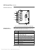
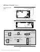
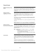
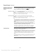
Figure 2-4. 565-222 & 565-368 Standard Slave PCB Assembly
Table 2-4 describes the I/O connectors on the Standard Slave PCB Assembly
(refer to Figure 2-4 for the location of these connectors).
Table 2-4. 565-222 and 565-368 Standard Slave I/O Connectors
Label Description
TB1 – TB4 I/O Connections for NAC’s, IAC’s & Control Contacts
TB5 Mapnet Interface Connector
JW1 – JW2 Selects U11 size
• JW1-
IN
, JW2-
OUT
: 32K
• JW1-
OUT
, JW2-
IN
: 64K
SW1 Communication
• 1–7
ON
; 8
OFF
(Address 01, Baud rate 9600 )
SW2 Batteries selection
• Standard: 1–3
ON
, 4
OFF
for lead acid battery
P1 – P4 I/O Configuration Plugs
P5 5V and 28V Power Input From Power I/O Interface
P6 & P7 System Comm, Coded Bus and 5V& 28V To Master &
Peripheral Cards
P8 36V Mapnet Power Connector
P9 Interface Connector for Power I/O Interface Card
Communications
4020 Standard Slave,
Continued
Standard Slave PCB Layout
Standard Slave PCB
Assembly I/O Connectors
P8
JW1 JW2
SW1
SW2
P9
P5
P6
P7
P1
TB1
TB2
TB3
TB4
P2
P3
P4
TB5
U11
Technical Manuals Online! - http://www.tech-man.com