BC57Q Intel® Socket LGA1156 Core i7/i5/i3 32nm/45nm CPU ATX Motherboard User’s Manual Edition 1.
FCC Statement THIS DEVICE SUPPORTS PART 15 FCC RULES. OPERATION IS SUBJECT TO THE FOLLOWING TWO CONDITIONS: (1) THIS DEVICE MAY NOT CAUSE HARMFUL INTERFERENCE. (2) THIS DEVICE MUST ACCEPT ANY INTERFERENCE RECEIVED INCLUDING INTERFERENCE THAT MAY CAUSE UNDESIRED OPERATION. THIS EQUIPMENT HAS BEEN TESTED AND FOUND TO COMPLY WITH THE LIMITS FOR A CLASS "A" DIGITAL DEVICE, PURSUANT TO PART 15 OF THE FCC RULES.
Disclaimer BCM Advanced Research reserves the right to make changes, without notice, to any product, including circuits and/or software described or contained in this manual in order to improve design and/or performance.
A Message to the Customer BCM Customer Services Each and every BCM product is built to the most exacting specifications to ensure reliable performance in the harsh and demanding conditions typical of industrial environments. Whether your new BCM device is destined for the laboratory or the factory floor, you can be assured that your product will provide the reliability and ease of operation for which the name BCM has come to be known. Your satisfaction is our primary concern.
Product Warranty BCM warrants to you, the original purchaser, that each of its products will be free from defects in materials and workmanship for two years from the date of purchase. This warranty does not apply to any products which have been repaired or altered by persons other than repair personnel authorized by BCM, or which have been subject to misuse, abuse, accident or improper installation. BCM assumes no liability under the terms of this warranty as a consequence of such events.
Manual Objectives This manual describes in detail the BCM BC57Q Main board. We strongly recommend that you study this manual carefully before attempting to interface with BC57Q or change the standard configurations. Whilst all the necessary information is available in this manual we would recommend that unless you are confident, you contact your supplier for guidance. Please be aware that it is possible to create configurations within the CMOS RAM that make booting impossible.
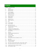
Contents Chapter 1: System Setup ..............................................................................................12 1.1 Welcome! ......................................................................................................................................12 1.2 Packing Contents..........................................................................................................................12 1.3 Special Features .............................................................
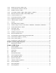
1.10.5 S/PDIF-Out Connector: SPDIF_OUT1 .........................................................................................41 1.10.6 Front Panel Audio Connector: FPAUD1........................................................................................42 1.10.7 Amplifier Connector: JAMP1.........................................................................................................43 1.10.8 Front USB2.0 Headers: USB67, USB89, USB1011, USB1213........................................
3.5.8 MPS Configuration........................................................................................................................68 3.5.9 Remote Access Configuration ......................................................................................................69 3.5.10 Trusted Computing .......................................................................................................................70 3.5.11 USB Configuration ................................................
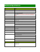
Mainboard Specifications Model BC57Q Processor Socket LGA1156 supports Core i7/i5/i3 32nm/45nm CPU Chipset Intel® Q57 Memory 4 x 240 Pin DIMM sockets supports DDR3 memory module (1.5V) 1066/1333 MHz up to 16GB (4GB maximum/slot) Display Intel® GMA HD (Needs to use Intel Processor that provides “Intel HD Graphics” feature) SATA 5 x SATA II connectors supports 3.
1 x PCI-E x 1 slot PCI 4 x PCI slots Onboard I/O Headers SATA 5 x Std.
Chapter 1: System Setup This chapter describes the mainboard features and the new technologies it supports 1.1 Welcome! The mainboard delivers a host of new features and latest technologies, making it another line of BCM long life mainboards! Before you start installing the mainboard, and hardware devices on it, check the items in your package with the list below. If any of the items listed below is damaged of missing, please contact with your vendor. 1.
1.3 1.3.1 Special Features Product Highlights • Intel® i7/i5/i3 LGA1156 32nm/45nm Processor Support This mainboard supports the Intel® Intel® i7/i5/i3 32nm/45nm processors in the LGA1156 package. • Intel® Q57 Express Chipset The Intel® Q57 PCH provides all business with more effective costs management, safer computing environment, and deploys more responsive PCs.
1.4 Before you proceed Take note of the following precautions before you install mainboard components or change any mainboard settings. • Unplug the power cord from the wall socket before touching any component inside the system. • Use a grounded wrist strap or touch a safely grounded object or to a metal object, such as the power supply case, before handling components to avoid damaging them due to static electricity. • Hold components by the edges to avoid touching the ICs on them.
1.5 Mainboard Overview Before you install the mainboard, study the configuration of your chassis to ensure that the mainboard fits into it. Make sure to unplug the power cord before installing or removing the mainboard. Failure to do so can cause you physical injury and damage mainboard components. 1.5.1 Placement Direction When installing the mainboard, make sure that you place it into the chassis in the correct orientation.
1.5.2 Mounting Holes Place the screws into the mounting holes indicated by green squares to secure the mainboard to the chassis. Do not over-tighten the screws! Doing so may damage the mainboard.
1.5.3 Onboard LEDs The mainboard comes with a “Power On LED” (green) and one “Standby Power LED” (red) to indicate the system status. When the “Standby Power LED” lights on: It means the system is either in the standby state, or the power cable is still connected to the power source. The “Power On LED” lights on/off to indicate that the system status, in sleep mode, or in soft-off mode.
1.5.
1.5.5 Layout Content List • 1.5.5.1 Slots Label DIMMA1 Function Note 240-pin DIMM slot 1 1. If there is only one memory Page 31 module being installed in the system, install it on this slot first. 2. If there are only two memory modules being installed in the system, install these 2 modules on “DIMMA1” and “DIMMB1” first.
• 1.5.5.3 Internal Headers Label Function Note Page ATX12V1 ATX Power Connector 2 x 2 header 35 EATXPWR1 ATX Power Connector 12 x 2 header 35 SATA1, Serial ATA Connectors 1~5 7-pin header 38 CPU_FAN1 CPU Fan Connector 4 x 1 wafer, pitch 2.54mm 39 CHA_FAN1 Chassis Fan Connector 4 x 1 wafer, pitch 2.54mm 39 SYS_FAN1 System Fan Connector 4 x 1 wafer, pitch 2.54mm 39 JCASE1 Chassis Intrusion Connector 2 x 1 header, pitch 2.
• 1.5.5.4 Back Panel Connectors Label Function Note Page KBMS1 PS/2 keyboard and mouse 6-pin Mini-Din 36, 37 VGA_DVI1 VGA Connector D-sub 15-pins, female 36, 37 DVI Connector Dual Link DVI-D; 24-pins ESATA+USB45 ESATA Connector 36, 37 USB Connector x 2 LAN1_USB01 RJ-45 Ethernet Connector x 1 36, 37 USB 3.0 Connector x 2 LAN2_USB23 RJ-45 Ethernet Connector x 1 36, 37 USB Connector x 2 AUDIO1 Line-in Port, Line-out Port, 5.
1.6 Central Processing Unit (CPU) This mainboard supports the Intel® LGA1156 socket for Intel® Core™ i7/i5/i3 desktop processors. If you do not have the CPU cooler, consult with your dealer before turning on the system. • Your boxed Intel® LGA1156 processor package should come with installation instructions for the CPU, fan, heatsink, and the retention assembly. • Upon purchase of the mainboard, make sure that the PnP cap is on the socket and the socket pins are not bent.
1.6.1 Installing the CPU To install a CPU 1. Locate the CPU socket (LGA1156 Socket) on the mainboard. 2. Unlatch the “CPU Socket Lever” by pressing the lever down and move it away from the main structure of the socket. To prevent damage to the socket pins, do not remove the “CPU Socket Cover” (PnP cap) unless you are installing a CPU.
3. Lift the load lever up in the direction of the arrow to a 135° angle, so the metal “CPU Socket Cover” can also be lifted. 4. The CPU socket has a plastic protection cap installed on it (black color, a.k.a. “CPU Socket Cover”, or “PnP cap”) in order to protect the socket pins from damage. If you are going to install a CPU, remove the plastic protection cap away from the CPU socket by lifting it up (NOTE: Please do not discard this plastic protection cap.
5. There are two notches on the CPU itself (one on each side), and there are two “Socket Alignment keys” on the CPU socket as well. Line up the two CPU notches with the “Socket Alignment Keys” on the socket, and insert the CPU into the CPU socket slowly. 6. Visually inspect if the CPU is seated into the CPU socket evenly. The “Socket Alignment keys” should fit into the CPU notches.
7. Close the “CPU Socket Cover” by lowering down the “CPU Socket Lever”. Make sure the “CPU Socket Front Plates” are sliding underneath the “Shoulder Screw Cap”. 8. Secure the “CPU Socket Cover” by keep pressing down the “CPU Socket Lever” and move it toward and underneath the “Load Plate Tab”. The CPU fits in only one correct orientation, DO NOT force the CPU into the socket. Otherwise, it might damage the CPU and/or the CPU socket.
1.6.2 Installing the CPU Heatsink and Fan The Intel LGA1156 processor requires a specially designed heatsink and fan assembly to ensure optimum thermal condition and performance. • When you purchase a boxed Intel® processor, the package includes the CPU fan and heatsink assembly. If you buy a CPU separately, make sure that you use only Intel®-certified multi-directional heatsink and fan. • Your Intel® LGA1156 heatsink and fan assembly comes in a push-pin design and requires no tool to install.
Make sure to orient each fastener with the narrow end of the groove pointing outward. (The photo shows the groove shaded for emphasis.) 2. Push down two fasteners at a time in a diagonal sequence to secure the heatsink and fan assembly in place. 3. Connect the CPU fan cable to the connector on the motherboard labeled “CPU_FAN1”. 1. Do not forget to connect the CPU fan connector. Insufficient air flow inside the system chassis may damage the mainboard components.
1.6.3 Uninstalling the CPU Heatsink and Fan. To uninstall the CPU heatsink and fan: 1. Disconnect the CPU fan cable from the connector on the mainboard. 2. Rotate each fastener counterclockwise. 4. Pull up two fasteners at a time in a diagonal sequence to disengage the heatsink and fan assembly from the mainboard.
5. Rotate each fastener clockwise to ensure correct orientation when reinstalling. The narrow end of the groove should point outward after resetting. (The photo shows the groove shaded for emphasis.
1.7 1.7.1 System Memory Overview The mainboard comes with four 240-pin Double Data Rate 3 (DDR3) Dual Inline Memory Modules (DIMM) slots. You may ONLY use 1066MHz (PC3-8500), or 1333MHz (PC3-10600); Non-ECC, Un-buffered 1.5V DDR3 memory modules on this board (4GB maximum for each slot). DDR3 DIMMs are notched differently to prevent installation on a DDR2 DIMM socket. The following figure illustrates the location of memory slots.
1.7.2 Dual-Channel Mode Population Rule In Dual-Channel mode, the memory modules can transmit and receive data with two data bus lines simultaneously. Enabling Dual-Channel mode can enhance the system performance. Please refer to the following illustrations for population rules under Dual-Channel mode. • When install only one DDR3 memory module, install it on “DIMMA1” slot ONLY. • When install only two DDR3 memory module, install them on “DIMMA1” and “DIMMB1” slots ONLY.
1.7.3 Installing DIMM Make sure to unplug the power supply before adding or removing DIMMS or other peripherals from the system. Failure to do so may cause severe damage to both the mainboard and the peripherals. 1. Unlock a DIMM socket by pressing the retaining clips outward. 2. Align a DIMM on the socket such that the notch on the DIMM matches the break on the socket. 3. Firmly insert the DIMM into the socket until the retaining clips snap back in place and the DIMM is properly seated.
1. A DDR3 memory module is keyed with a notch so that it fits in only one direction. 2. DO NOT force the memory module into the socket in order to avoid damaging the memory module and the slot. 3. DDR3 memory modules are not interchangeable with DDR or DDR2. 4. DDR3 standard IS NOT backward compatible. You shall only install the DDR3 memory modules on this mainboard. 5. To enable the system boot-up successfully, always install the memory module into the DMMA1 slot first.
1.7.4 Removing DIMM Follow these steps to remove a DIMM. 1. Simultaneously press the retaining clips outward to unlock the DIMM. 2. Remove the DIMM from the socket.
1.8 Power Supply 1.8.1 ATX Power Connectors: EATXPWR1, ATX12V1 These ATX power connectors provide connections from power supply unit (PSU) to the mainboard. Both connectors need to be installed in order for the mainboard to function properly. The power supply plugs are designed to fit with these ATX power connectors in one orientation only. To connect these power supply plugs; find the proper orientation first, and then push down the power supply plugs firmly until the connectors are completely fit.
1.9 1.9.1 Back Panel Back Panel Connectors Item Name Function 1 KBMS1 PS/2 Mouse Description This port is for a PS/2 mouse. Connector 2 DVI DVI Video Port 3 USB45 USB 2.0 Connectors DVI-D 24-Pin Connector. These two 4-pin Universal Serial Bus (USB) ports are available for connecting USB2.0 devices. 4 LAN1/ Gigabit LAN LAN2 (RJ-45) Connectors This port allows Gigabit connection to a Local Area Network (LAN) through a network hub. Refer to the table below for the LAN port LED indications.
Item Name Function 9 USB01 USB 2.0 Connectors Description These two 4-pin Universal Serial Bus (USB) ports are available for connecting USB 2.0 devices. (USB 3.0 Optional) 10 ESATA ESATA Connector This port connects to an ESATA device (ESATA cable required). 11 VGA VGA Video Port This 15-pin port is for a VGA monitor or other VGA-compatible devices. 12 KBMS1 PS/2 Keyboard This port is for a PS/2 keyboard.
1.10 Connectors/ Headers 1.10.1 Serial ATA Connectors: SATA0, SATA1, SATA2, SATA3, SATA4 Please do not fold the Serial ATA cable into 90-degree angle. Otherwise, data loss may occur during data transmission.
1.10.2 Fan Power Connectors: CPU_FAN1, CHA_FAN1, SYS_FAN1 The fan power connectors support system cooling fan with +12V. When connecting the wire to these fan connectors, please note that the red wire is designated as “Power” and should be connected to “+12V” pin; the black wire is designated as “Ground” and should be connected to “GND”. In order to take the advantage of System Hardware Monitor, be sure to use the fan which is specifically designed with speed sensor.
1.10.4 CD-In Connector: CDIN1 This connector is provided for external audio input. 1.10.5 S/PDIF-Out Connector: SPDIF_OUT1 This connector is used to connect S/PDIF (Sony & Philips Digital Interconnect Format) interface for digital audio transmission.
1.10.6 Front Panel Audio Connector: FPAUD1 This connector allows you to connect the front panel audio and is compliant with Intel® Front Panel I/O Connectivity Design Guide.
1.10.7 Amplifier Connector: JAMP1 This header provided amplified audio signals to external speakers (2-channels). The dB level can be adjusted under BIOS. 1.10.8 Front USB2.0 Headers: USB67, USB89, USB1011, USB1213 This connector is compliant with Intel® I/O Connectivity Design Guide, which is ideal for connecting high-speed USB peripherals such as USB HDD, USB digital cameras, USB MP3 players, USB printers, etc. Be sure the pins of VCC and GND is connected to the connector correctly.
1.10.9 Serial Port Connectors: COM1, COM2, COM3, COM4 This connector is a 16550A high speed communication port that sends/receives 16 byte FIFOs. 1.10.
1.10.11 Front Panel Connectors: F_PANEL1 These connectors are for electrical connections to the front panel switches and LEDs. The “F_PANEL1” connector is compliant with Intel® Front Panel I/O Connectivity Design Guide. 1.10.
1.10.13 LANLED Header: LANLED1 The “LANLED1” header provides the option for front panel to display the LED status simultaneously with the corresponding RJ45 port. For the LAN speed LED connection, a “Dual-band Common Cathode LED” (3-pin LED) is recommended.
1.11 Jumpers 1.11.1 Clear CMOS Jumper: JCMOS1 There is a CMOS RAM onboard that has a power supply from an external battery to keep the data of system configuration. For normal state (default), the jumper is set on pin location 1 and 2. To clear the CMOS, set the jumper to pin location 2 and 3 for at least 30 seconds while the system is off. 1. You can clear CMOS by shorting pin 2-3 for at least 30 seconds (while the system is OFF), then place the jumper back to pin 1-2 for normal operation. 2.
1.11.2 COM Port Ring-in/ +12V/ +5V Power Select: JCOMPWR1, JCOMPWR2, JCOMPWR3 These headers provide ring-in, or 5V, or 12V on the com ports. 1.11.3 ATX/AT Mode Selection: PSON1 This header provides the option to boot the system in the form of ATX mode (default) or AT mode. When the system is set in AT mode, the system power on/off will be controlled directly by the power switch on power supply. And some of the power saving modes will not function as ATX mode provided. 1.11.
1.12 The Expansion Slots In the future, you may need to install expansion cards. The following sub-sections describe the expansion slots and the expansion cards that they support. Make sure to unplug the power cord before adding or removing expansion cards. Failure to do so may cause you physical injury and damage mainrboard components. 1.12.1 Installation of Expansion Card To install an expansion Card: 1.
1.12.3.1 PCI-E x 16 Slot: PCIEX16_1, PCIEX4_1 • The PCIEX16_1 slot supports PCI-E x16 graphic card. • When PCIEX16_1 slot installed with PCI-E x16 graphic card, there will be no video output from onboard CRT and DVI port. • The PCIEX4_1 supports PCI-E transfer rate up to 4x ONLY. • When PCIEX4_1 slot installed with PCI-E x4 or PCI-E x1 card, there will be no video output from onboard CRT and DVI port.
Chapter 2: Starting Up the System 2.1 Starting Up Your System 1. After all connections are made, close your computer case cover. 2. Be sure all the switches are off, and check that the power supply input voltage is set to the local voltage, usually in-put voltage is 220V∼240V or 110V∼120V depending on your country’s voltage used. 3. Connect the power supply cord into the power supply located on the back of your system case according to your system user’s manual. 4.
“Shut down” and then click “Shut down the computer” The power supply should turn off after windows shut down.
Chapter 3: BIOS Setup Warnining: Before flashing the BIOS, please be sure to make the following adjustments on the system: 1. Fully disabled the iAMT feature (through Intel ME management utility during system post). 2. Flash the mainboard with memory module installed on memory slot “DIMMB2” ONLY. No memory module occupied on memory slots “DIMMA1”, “DIMMA2” and “DIMMB1” during the BIOS flash process. 3.
3.2 Entering BIOS Setup Menu Power on the computer and by pressing immediately allows you to enter BIOS Setup Menu. If you are not able to enter the BIOS menu but you still wish to enter Setup, restart the system to try again by turning it OFF then ON or pressing the “RESET” button on the system case. You may also restart by simultaneously pressing , and keys. The items under each BIOS category described in this chapter are under continuous update for better system performance.
3.4 Main Setup When you first enter the Setup Utility, you will enter the Main setup screen. You can always return to the Main setup screen by selecting the Main tab. There are two Main Setup options. They are described in this section. The Main BIOS Setup screen is shown below. y System Time/System Date Use this option to change the system time and date. Highlight System Time or System Date using the keys. Enter new values through the keyboard.
3.5 Advanced BIOS Setup Select the Advanced tab from the setup screen to enter the Advanced BIOS Setup screen. You can select any of the items in the left frame of the screen, such as SuperIO Configuration, to go to the sub menu for that item. You can display an Advanced BIOS Setup option by highlighting it using the keys. All Advanced BIOS Setup options are described in this section. The Advanced BIOS Setup screen is shown below. The sub menus are described on the following pages.
3.5.1 CPU Configuration Setting You can use this screen to select options for the CPU Configuration Settings. Use the up and down keys to select an item. Use the and keys to change the value of the selected option. A description of the selected item appears on the right side of the screen. The settings are described on the following pages.
3.5.2 IDE Configuration Setting You can use this screen to select options for the IDE Configuration Settings. Use the up and down keys to select an item. Use the and keys to change the value of the selected option. A description of the selected item appears on the right side of the screen. The settings are described on the following pages. SATA Configuration The choices of SATA configuration are Disabled, Compatible, and Enhanced.
IDE Detect Time Out (Sec) Set this option to stop the AMIBIOS from searching for IDE devices within the specified number of seconds. Basically, this allows you to fine-tune the settings to allow for faster boot times. Adjust this setting until a suitable timing that can detect all IDE disk drives attached is found. The default setting is 35. Option Description 0 This value is the best setting to use if the onboard IDE controllers are set to a specific IDE disk drive in the AMIBIOS.
3.5.3 SuperIO Configuration You can use this screen to select options for the Super I/O settings. Use the up and down keys to select an item. Use the and keys to change the value of the selected option. The settings are described on the following pages. The screen is shown below. Serial Port1 Address This option configures serial port 1 base addresses. Serial Port2 Address This option configures serial port 2 base addresses.
Serial Port 4 Address This option configures serial port 4 base address. Serial Port 4 IRQ This option configures serial port 4 base IRQ.
3.5.4 Hardware Health Configuration You can use this screen to select options for the Hardware Health settings. Use the up and down keys to select an item. Use the and keys to change the value of the selected option. The settings are described on the following pages. The screen is shown below. Chassis Intrusion This item selects the chassis intrusion. The choices are Disabled or Enabled. System Temperature This shows you the current temperature of system.
3.5.5 ACPI Configuration You can use this screen to select options for the ACPI settings. Use the up and down keys to select an item. Use the and keys to change the value of the selected option. The settings are described on the following pages. The screen is shown below.
General ACPI Configuration This item allows you to set general ACPI Configuration. Suspend mode Allows you to select the Advanced Configuration and Power Interface(ACPI) state to be used for system suspend. [Auto] The system automatically configures the ACPI suspend mode. [S1(POS) only] Sets the ACPI suspend mode to S1/POS (Power On Suspend).
Chipset ACPI Configuration This item allows you to set South Bridge ACPI Configuration. APIC ACPI SCI IRQ Enable/Disable APIC ACPI SCI IRQ. High Performance Event Timer Enable/Disable High performance event timer.
3.5.6 AHCI Configuration AHCI Port1-6 [XXXX] Displays the status of auto-detection of SATA devices. AHCI Port1-6 [Auto] [Auto] Allows automatic selection of the device type connected to the system. [Not Detected] Selects this option if no SATA devices are installed.
3.5.7 ASF Configuration ASF Support ASF (Alert Standard Format) provides standards-based alerting and remote control. Both the alerting and remote control capabilities of ASF are hardware-based and local to the networking solution on managed systems. This allows these solutions CPU and OS independence, providing a persistent connection with the management console.
3.5.8 MPS Configuration MPS Revision This feature is only applicable to multiprocessor motherboards as it specifies the version of the Multi-Processor Specification (MPS) that the motherboard will use. The MPS is a specification by which PC manufacturers design and build Intel architecture systems with two or more processors.
3.5.9 Remote Access Configuration You can disable or enable the BIOS remote access feature here. This function is used to redirect the console from the serial port. The Optimal and Fail-Safe default setting is Disabled. If you want to use SOL, which is provided by Intel AMT, you have to enable the Remote access feature.
3.5.10 Trusted Computing You can use this screen to select options for the Intel Trusted Computing settings. Use the up and down keys to select an item. Use the and keys to change the value of the selected option. The settings are described on the following pages. The screen is shown below. TCG/TPM SUPPORT Enable or disable TPM TCG (TPM 1.1/1.2) support in BIOS.
3.5.11 USB Configuration Legacy USB Support (This item is offered in QG2 SKU) Enables support for legacy USB. Auto option disables legacy support if no USB devices are connected. USB 2.0 Controller Mode This item allows you to select Hi-Speed (480 Mbps) or Full-Speed (12 Mbps). Legacy USB1.1 HC Support (This item is offered in QG2 SKU) Allows the system to detect the presence of USB devices at startup. If detected, the USB controller legacy mode is enabled. If no USB device is detected.
3.6 Advanced PCI/PnP Settings Select the PCI/PnP tab from the setup screen to enter the Plug and Play BIOS Setup screen. You can display a Plug and Play BIOS Setup option by highlighting it using the keys. All Plug and Play BIOS Setup options are described in this section. The Plug and Play BIOS Setup screen is shown below. 3.6.1 Clear NVRAM This item is to clear NVRAM during system boot. The choices are No or Yes. 3.6.
3.6.3 PCI Latency Timer Set this value to allow the PCI Latency Timer to be adjusted. This option sets the latency of all PCI devices on the PCI bus. The default setting is 64. Option Description 32 This option sets the PCI latency to 32 PCI clock cycles. 64 This option sets the PCI latency to 64 PCI clock cycles. This is the default setting. 96 This option sets the PCI latency to 96 PCI clock cycles. 128 This option sets the PCI latency to 128 PCI clock cycles.
3.7 Boot Settings Select the Boot tab from the setup screen to enter the Boot Setup screen. You can display a Boot Setup option by highlighting it using the keys. All Boot BIOS Setup options are described in this section. The Boot BIOS Setup screen is shown below.
3.7.1 Boot Settings Configuration You can use this screen to select options for the Boot settings. Use the up and down keys to select an item. Use the and keys to change the value of the selected option. The settings are described on the following pages. The screen is shown below. Quick Boot The default setting is Enabled. Option Description Disabled Set this value to allow the BIOS to perform all POST tests.
Bootup Num-Lock Set this value to allow the Number Lock setting to be modified during boot up. The default setting is On. Option Description Off This option does not enable the keyboard Number Lock automatically. To use the 10-keys on the keyboard, press the Number Lock key located on the upper left-hand corner of the 10-key pad. The Number Lock LED on the keyboard will light up when the Number Lock is engaged.
3.8 Security Setup Select Security Setup from the Setup main BIOS setup menu. All Security Setup options, such as password protection and virus protection, are described in this section. To access the sub menu for the following items, select the item and press : Change Supervisor / User Password Provides for either installing or changing the password.
3.9 Chipset Setup Select the Chipset tab from the setup screen to enter the Chipset BIOS Setup screen. You can select any of the items in the left frame of the screen, such as CPU Configuration, to go to the sub menu for that item. You can display a Chipset BIOS Setup option by highlighting it using the keys. All Chipset BIOS Setup options are described in this section. The Chipset BIOS Setup screen is shown below.
3.9.1 North Bridge Configuration You can use this screen to select options for the North Bridge Configuration. Use the up and down keys to select an item. Use the and keys to change the value of the selected option. Note: The North Bridge Configuration setup screen varies depending on the supported North Bridge chipset. Memory Remap Feature Enabling this feature allows the system to use memory capacity larger than 4GB, disabling this limits system memory capacity no more than 4GB.
Memory Hole This setting allows the user to reserve the 1MB of memory required by some legacy add-on cards. DRAM Margin Ranks This allows the user to enable or disable the DRAM Margin Ranks function. Initiate Graphic Adapter This setting allows the user to select which graphics controller to be the primary graphic device when booting up. IGD Graphics Mode Select Allows you to decide whether to use the integrated GPU and select the amount of memory used by the integrated GPU.
Video Function Configuration DVMT Mode Select Use this field to select the memory to allocate for video memory. The choice is DVMT. DVMT/Fixed Memory Size Specify the size of DVMT/system memory to allocate for video memory.
3.9.2 South Bridge Configuration You can use this screen to select options for the South Bridge Configuration. South Bridge is a chipset on the motherboard that controls the basic I/O functions, USB ports, audio functions, modem functions, IDE channels, and PCI slots. Use the up and down keys to select an item. Use the and keys to change the value of the selected option.
LAN2 Controller Enables or disables the LAN2 controller. LAN2 Option-ROM Enables or disables LAN2 option-ROM. Resume On LAN2 Enables or disables LAN2 resuming. Resume on Ring Enabling this will allow the system to be woken up by modem ringing. Resume on RTC Alarm Enabling this will allow the system to be woken up by RTC alarm. HDA Controller Enables or disables the High Definition audio controller. Internal HDMI Enables or disables the HDMI controller. SLP_S4# Min.
3.9.3 Intel AMT Configuration Intel AMT Support Enables or disables Intel AMT function. Force IDER Enables or disables IDE redirection under Intel AMT support. Force SOL Enables or disables SOL under Intel AMT support. If you enable SOL here, the remote access has been set as enable which is described in section 2.4.9 Unconfigure AMT/ME This item allows the user to clear ME settings. Activate Remote Assistance This item allows the user to enable or disable remote assistance features.
3.9.4 Intel VT-d Configuration You can use this screen to select options for the Intel VT-d settings. Use the up and down keys to select an item. Use the and keys to change the value of the selected option. The settings are described on the following pages. The screen is shown below. Intel VT-d The Choices are enabled or disabled the Intel VT-d.
3.9.5 ME Subsystem Configuration Boot Block HECI Message This allows the user to enable or disable Boot Block HECI messaging between system BIOS code and ME code. HECI Message This allows the user to enable or disable HECI messaging between system BIOS code and ME code. End of POST S5 HECI Message Enabling this will let system BIOS code to inform ME code ending of POST S5 via HECI messaging. ME HECI Configuration ME-HECI This allows the user to enable or disable HECI function of ME.
3.9.6 VE Subsystem Configuration Intel VE Subsystem Configuration VE refers to Intel Virtualization Engine. Access to the PBA area is permitted via the VE by using the VE Command Interface (VECI), or via the Intel ME by using the Intel AT-d Host Command Interface (DHCI); which uses HECI. The VE can ensure that access requests outside the PBA ranges are prevented given that PBA code executes on the host processor.
3.10 Exit Menu Select the Exit tab from the setup screen to enter the Exit BIOS Setup screen. You can display an Exit BIOS Setup option by highlighting it using the keys. All Exit BIOS Setup options are described in this section. The Exit BIOS Setup screen is shown below.
3.10.1 Save Changes and Exit When you have completed the system configuration changes, select this option to leave Setup and reboot the computer so the new system configuration parameters can take effect. Select Exit Saving Changes from the Exit menu and press . Save Configuration Changes and Exit Now? [Ok] [Cancel] Select Ok to save changes and exit. 3.10.2 Discard Changes and Exit Select this option to quit Setup without making any permanent changes to the system configuration.