
Data Sheet


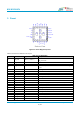


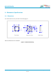

Table Of Contents

Bluetooth 5.1 Dual Mode Transceiver Module Based on CC2564C
info@bdecomm.com
BDE Technology Inc.
Datasheet
BDE-BD2564CN
7 / 14
Pin #
Pin Name
Type
Description
22
AUD_FSYNC
DIO, PD
PCM frame sync, fail-safe
23
NC
-
Not connected
24
TX_DBG
DO, PU
Internal debug messages
25
GND
GND
Power ground
26
GND
GND
Power ground
27
GND
GND
Power ground
28
GND
GND
Power ground
29
GND
GND
Power ground
30
GND
GND
Power ground
31
GND
GND
Power ground
32
GND
GND
Power ground
33
GND
GND
Power ground
Note 1: DI stands for Digital Input, DO stands for Digital Output, DIO stands for Digital Input-Output, AIO stands for Analog
Input Ouput;
Note 2: PU stands for internal Pull-Up, PD stands for internal Pull-Down.
3. Characteristics
All MIN/MAX specification limits are guaranteed by design, production testing and/or statistical characterization. Typical
values are based on characterization results at default measurement conditions and are informative only.
Default measurement conditions (unless otherwise specified): VDD_IN = 3.6 V, VDD_IO = 1.8V, TA = 25 ℃. All radio
measurements are performed with standard RF measurement equipment.
3.1. Absolute Maximum Ratings
Stresses beyond those listed under Absolute Maximum Ratings may cause permanent damage to the device. These are
stress ratings only, so functional operation of the device at these or any other conditions beyond those indicated in the
operational sections of the specification are not implied. Exposure to Absolute Maximum Rating conditions for extended
periods may affect device reliability.
Table 3-1. Absolute Maximum Ratings
PARAMETER
MIN
MAX
UNIT
Notes
VDD_IN
-0.5
4.8
V
VDD_IO
-0.5
2.415
V
Input voltage to analog pin
-0.5
2.1
V
BT_ANT
Input voltage to all other pins
-0.5
VDD_IO + 0.5
Bluetooth RF pin
8
dBm
Storage Temperature
-40
100
°C