
Data Sheet


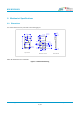

Table Of Contents

Bluetooth 5.1 Dual Mode Transceiver Module Based on CC2564C
info@bdecomm.com
BDE Technology Inc.
Datasheet
BDE-BD2564CA
6 / 14
2. Pinout
19 AUD_IN
20 AUD_OUT
21 AUD_CLK
22 AUD_FSYNC
23 NC
24 TX_DBG
GND
NC
GND
HCI_RTS
HCI_RX
HCI_TX
HCI_CTS
GND
31
6
5
4
3
2
1
30
VDD_IN 12
NC 11
NC 10
GND 9
SLOW_CLK_IN 8
GND 7
32
13
14
15
16
17
18
33
GND
GND
NC
GND
nSHUTD
GND
VDD_IO
GND
34 GND
GND 35
25
GND
26
GND
29
GND
27
GND
28
GND
Bottom View
Figure 2-1. Pinout Diagram Top View
Table 2-1 describes the definitions of the pins.
Table 2-1. Pin Description
Pin #
Pin Name
Type
Description
1
HCI_CTS
DI
(Note 1)
, PU
(Note 2)
HCI UART clear-to-send. The device can send data when
HCI_CTS is low
2
HCI_TX
DO, PU
HCI UART data transmit
3
HCI_RX
DI, PU
HCI UART data receive
4
HCI_RTS
DO, PU
HCI UART request-to-send. Host can send data when HCI_RTS
is low
5
GND
GND
Power ground
6
NC
-
Not connected
7
GND
DIO
GPIO, Sensor Controller
8
SLOW_CLK_IN
DI
32.768-kHz clock in, fail-safe
9
GND
GND
Power ground
10
NC
-
Not connected
11
NC
-
Not connected
12
VDD_IN
Power
Main power supply for the module (2.2 to 4.8 V)
13
GND
GND
Power ground
14
NC
-
Not connected
15
GND
GND
Power ground
16
nSHUTD
DI, PD
Shutdown input (active low)
17
GND
GND
Power ground
18
VDD_IO
Power
I/O power supply (1.8 V nominal)
19
AUD_IN
DI, PD
PCM data input, fail-safe
20
AUD_OUT
DO, PD
PCM data onput, fail-safe
21
AUD_CLK
DIO
(Note 1)
, PD
PCM clock, fail-safe