BDE-WF3235 Datasheet BDE Dual-Band WiFi MCU Module General Description The BDE-WF3235 module, is a 802.11abgn, IPv4 & IPv6 Low Energy module based on CC3235S/CC3235SF SoC. The module offers a unique combination of lower power, integration of all external components including dual band Ceramic Antenna at a very affordable cost. Created for IoT , the BDE-WF3235 module is a wireless module that integrates two physically separated on-chip MCUs, application processor and network processor.
BDE-WF3235 Datasheet BDE Dual-Band WiFi MCU Module • Single wide-voltage supply VBAT: 2.3 V to 3.6 V Advanced low-power modes: • Shutdown: 1 µA, Hibernate: 5.5 µA • Low-power deep sleep (LPDS): 120 µA • Idle connected (MCU in LPDS): 710 µA • RX traffic (MCU active): 59 mA • TX traffic (MCU active): 223 mA Wi-Fi TX power • 2.4 GHz: 16 dBm at 1 DSSS • 5 GHz: 15.1 dBm at 6 OFDM Wi-Fi RX sensitivity • 2.4 GHz: –94.5 dBm at 1 DSSS • 5 GHz: –89 dBm at 6 OFDM Additional integrated components 40.
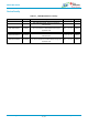
BDE-WF3235 Datasheet BDE Dual-Band WiFi MCU Module Device Family Table 0-1.BDE-WF3235 Device Family Part Number Core Chip Description Size (mm) Package BDE-WF3235SA32 CC3235S With 32Mbit external flash, with PCB antenna 20.5 × 23 × 2.4 SMD-63 BDE-WF3235SAU32 CC3235S With 32Mbit external flash, with U.FL connector for external antenna 20.5 × 23 × 2.
BDE-WF3235 Datasheet BDE Dual-Band WiFi MCU Module Contents General Description .......................................................................................................................................................... 1 Key Features ...................................................................................................................................................................... 1 Applications...............................................................................
BDE-WF3235 Datasheet BDE Dual-Band WiFi MCU Module 6.2.1 Power Supply Decoupling and Bulk Capacitors ......................................................................................69 6.2.2 Reset.......................................................................................................................................................69 6.2.3 Unused Pins..........................................................................................................................................
BDE-WF3235 Datasheet BDE Dual-Band WiFi MCU Module 1. References [1] CC3235S resources: https://www.ti.com/product/CC3235S [2] CC3235SF resources: https://www.ti.com/product/CC3235S/CC3235SF BDE Technology Inc. 6 / 77 info@bdecomm.
BDE-WF3235 Datasheet BDE Dual-Band WiFi MCU Module 2. Block Diagram BDE-WF3235 module is based on the TI Instruments CC3235S/CC3235SF SoC. With an integrated 32Mbit flash, 40MHz XTAL and a dual band Ceramic Antenna, it allows faster time to market at reduced development cost. The module, as seen in Figure 1, comprises of: - 32 Mbit SPI Flash - 40MHz XTAL - 32.768kHz XTAL - 2 filters - a SPDT - a diplexer - a dual band PCB trace antenna / U.
BDE-WF3235 Datasheet BDE Dual-Band WiFi MCU Module CC3235S/CC3235SF External Antenna RF-ABG BDE-WF3235SN32 BDE-WF3235SFN32 CC3235S/CC3235SF PCB Trace Antenna Jumper Resistor Jumper Resistor U.FL Connector BDE-WF3235SA32 BDE-WF3235SAU32 BDE-WF3235SFA32 BDE-WF3235SFAU32 Figure 2-1. BDE-WF3235 Module Block Diagram - Confidential BDE Technology Inc. 8 / 77 info@bdecomm.
BDE-WF3235 Datasheet BDE Dual-Band WiFi MCU Module 3. Terminal Configuration and Functions /RF_ABG 3.1 Pin Diagram BDE-WF3235 Figure 3-1. Pin Diagram Bottom View 3.2 Pin Attributes and Pin Multiplexing Table 3-1.
BDE-WF3235 Datasheet BDE Dual-Band WiFi MCU Module Pin # Pin Name Type(1) 13 FLASH_SPI_MISO I External serial flash programming: SPI data in 14 FLASH_SPI_nCS_IN I External serial flash programming: SPI chip select (active low) 15 FLASH_SPI_CLK I External serial flash programming: SPI clock 16 GND – Ground 17 FLASH_SPI_MOSI O External serial flash programming: SPI data out 18 JTAG_TDO I/O JTAG TDO output.
BDE-WF3235 Datasheet BDE Dual-Band WiFi MCU Module 43 GND – Pin # Pin Name Type(1) 44 GPIO0 I/O Ground Description GPIO(2) 45 NC – 46 GPIO1 I/O GPIO(2) 47 GPIO2 I/O GPIO(2) 48 GPIO3 I/O GPIO(2) 49 GPIO4 I/O GPIO(2) 50 GPIO5 I/O GPIO(2) 51 GPIO6 I/O GPIO(2) 52 GPIO7 I/O GPIO(2) 53 GPIO8 I/O GPIO(2) 54 GPIO9 I/O GPIO(2) 55 GND – Thermal ground 56 GND – Thermal ground 57 GND – Thermal ground 58 GND – Thermal ground 59 GND – Thermal ground 60
BDE-WF3235 BDE Dual-Band WiFi MCU Module Datasheet Note If an external device drives a positive voltage to the signal pads and the BDE-WF3235 module is not powered, DC is drawn from the other device. If the drive strength of the external device is adequate, an unintentional wakeup and boot of the BDE-WF3235 module can occur. To prevent current draw, we recommend any one of the following conditions: • All devices interfaced to the BDE-WF3235 module must be powered from the same power rail as the chip.
BDE-WF3235 BDE Dual-Band WiFi MCU Module Datasheet GENERAL PIN ATTRIBUTES Pkg. Pin Pin Alias Use Select as Wakeup Source FUNCTION Config. Addl. Analog Mux Muxed With JTAG Dig. Pin Mux Config. Reg. Dig. Pin Mux Config. Mode Value Signal Name Signal Description Signal Direction LPDS 0 GPIO11 GPIO I/O Hi-Z, Pull, Drive 1 I2C_SDA I2C data I/O (open drain) 3 4 5 GPIO11 GPIO14 BDE Technology Inc.
BDE-WF3235 BDE Dual-Band WiFi MCU Module Datasheet GENERAL PIN ATTRIBUTES Pkg. Pin 6 7 Pin Alias GPIO15 GPIO16 BDE Technology Inc. Use I/O I/O Select as Wakeup Source No No FUNCTION Config. Addl. Analog Mux No No Muxed With JTAG No No Dig. Pin Mux Config. Reg. GPIO_PAD_ CONFIG_15 (0x4402 E0DC) GPIO_PAD_ CONFIG_16 (0x4402 E0E0) PAD STATES Dig. Pin Mux Config.
BDE-WF3235 BDE Dual-Band WiFi MCU Module Datasheet GENERAL PIN ATTRIBUTES Pkg. Pin 8 9 10 Pin Alias GPIO17 GPIO12 GPIO13 BDE Technology Inc. Use I/O I/O I/O Select as Wakeup Source Yes No Yes FUNCTION Config. Addl. Analog Mux No No No Muxed With JTAG No No No Dig. Pin Mux Config. Reg. GPIO_PAD_ CONFIG_17 (0x4402 E0E4) GPIO_PAD_ CONFIG_12 (0x4402 E0D0) GPIO_PAD_ CONFIG_13 (0x4402 E0D4) PAD STATES Dig. Pin Mux Config.
BDE-WF3235 BDE Dual-Band WiFi MCU Module Datasheet 12 GT_CCP04 GENERAL PIN ATTRIBUTES Pkg. Pin 11 12 Pin Alias GPIO22 JTAG_TDI Use I/O I/O Select as Wakeup Source No No Timer capture port I FUNCTION Config. Addl. Analog Mux No No Muxed With JTAG Dig. Pin Mux Config. Reg. No GPIO_PAD_ CONFIG_22 (0x4402 E0F8) Muxed with JTAG TDI GPIO_PAD_ CONFIG_23 (0x4402 E0FC) PAD STATES Dig. Pin Mux Config.
BDE-WF3235 BDE Dual-Band WiFi MCU Module Datasheet GENERAL PIN ATTRIBUTES Pkg. Pin 18 Pin Alias JTAG_TDO Use I/O Select as Wakeup Source Yes FUNCTION Config. Addl. Analog Mux No Muxed With JTAG Muxed with JTAG TDO Dig. Pin Mux Config. Reg. GPIO_PAD_ CONFIG_ 24 (0x4402 E100) PAD STATES Dig. Pin Mux Config. Mode Value Signal Name Signal Description Signal Direction 1 TDO JTAG TDO. Reset default pinout.
BDE-WF3235 BDE Dual-Band WiFi MCU Module Datasheet GENERAL PIN ATTRIBUTES Pkg. Pin 23 Pin Alias SOP2 Use O only Select as Wakeup Source No FUNCTION Config. Addl. Analog Mux No Muxed With JTAG No Dig. Pin Mux Config. Reg. GPIO_PAD_ CONFIG_ 25 (0x4402 E104) PAD STATES Dig. Pin Mux Config.
BDE-WF3235 BDE Dual-Band WiFi MCU Module Datasheet 35 nRESET Global reset N/A N/A N/A N/A N/A nRESET 36 VBAT_ RESET Global reset N/A N/A N/A N/A N/A VBAT_RESET GENERAL PIN ATTRIBUTES Master chip reset. Active low. VBAT to nRESET pullup resistor N/A N/A N/A N/A N/A N/A N/A N/A FUNCTION Config. Addl. Analog Mux Muxed With JTAG PAD STATES Dig. Pin Mux Config. Reg. Dig. Pin Mux Config. Mode Value Signal Name Signal Description Signal Direction LPDS Hib nRESET = 0 Pkg.
BDE-WF3235 BDE Dual-Band WiFi MCU Module Datasheet GENERAL PIN ATTRIBUTES Pkg. Pin 44 45 Pin Alias GPIO0 NC Use I/O WLAN Select as Wakeup Source No N/A FUNCTION Config. Addl. Analog Mux User config not required N/A Muxed With JTAG No N/A Dig. Pin Mux Config. Reg. GPIO_PAD_ CONFIG_0 (0x4402 E0A0) N/A PAD STATES Dig. Pin Mux Config.
BDE-WF3235 BDE Dual-Band WiFi MCU Module Datasheet GENERAL PIN ATTRIBUTES Pkg. Pin 47 48 Pin Alias GPIO2 GPIO3 BDE Technology Inc. Use Analog input (up to 1.8 V)/ digital I/O Analog input (up to 1.8 V)/ digital I/O Select as Wakeup Source Yes No FUNCTION Config. Addl. Analog Mux Muxed With JTAG No No Dig. Pin Mux Config. Reg. GPIO_PAD_ CONFIG_2 (0x4402 E0A8) GPIO_PAD_ CONFIG_3 (0x4402 E0AC) Dig. Pin Mux Config.
BDE-WF3235 BDE Dual-Band WiFi MCU Module Datasheet GENERAL PIN ATTRIBUTES Pkg. Pin 49 50 Pin Alias GPIO4 GPIO5 BDE Technology Inc. Use Analog input (up to 1.8 V)/ digital I/O Analog input up to 1.5 V Select as Wakeup Source Yes No FUNCTION Config. Addl. Analog Mux Muxed With JTAG Yes No Dig. Pin Mux Config. Reg. GPIO_PAD_ CONFIG_4 (0x4402 E0B0) GPIO_PAD_ CONFIG_5 (0x4402 E0B4) Dig. Pin Mux Config.
BDE-WF3235 BDE Dual-Band WiFi MCU Module Datasheet GENERAL PIN ATTRIBUTES Pkg. Pin 51 52 53 Pin Alias GPIO6 GPIO7 GPIO8 Use I/O I/O I/O Select as Wakeup Source No No No FUNCTION Config. Addl. Analog Mux No No No Muxed With JTAG No No No Dig. Pin Mux Config. Reg. GPIO_PAD_ CONFIG_6 (0x4402 E0B8) GPIO_PAD_ CONFIG_7 (0x4402 E0BC) GPIO_PAD_ CONFIG_8 (0x4402 E0C0) Dig. Pin Mux Config.
BDE-WF3235 BDE Dual-Band WiFi MCU Module Pkg. Pin 54 Pin Alias GPIO9 Use I/O Select as Wakeup Source No Datasheet Config. Addl. Analog Mux No Muxed With JTAG No Dig. Pin Mux Config. Reg. GPIO_PAD_ CONFIG_9 (0x4402 E0C4) Dig. Pin Mux Config.
BDE-WF3235 BDE Dual-Band WiFi MCU Module Datasheet 3.3 Signal Descriptions Table 3-3. Signal Descriptions FUNCTION ADC BLE/2.4 GHz radio coexistence (2) Hostless mode JTAG / SWD BDE Technology Inc. SIGNAL NAME PIN NO. PIN TYPE SIGNAL DIRECTION DESCRIPTION ADC_CH0 47 I/O I ADC channel 0 input (maximum of 1.5 V) ADC_CH1 48 I/O I ADC channel 1 input (maximum of 1.5 V) ADC_CH2 49 I/O I ADC channel 2 input (maximum of 1.5 V) ADC_CH3 50 I I ADC channel 3 input (maximum of 1.
BDE-WF3235 BDE Dual-Band WiFi MCU Module FUNCTION SIGNAL NAME Datasheet PIN NO.
BDE-WF3235 BDE Dual-Band WiFi MCU Module FUNCTION GPIO Datasheet SIGNAL NAME PIN NO.
BDE-WF3235 BDE Dual-Band WiFi MCU Module FUNCTION Datasheet SIGNAL NAME PIN NO.
BDE-WF3235 BDE Dual-Band WiFi MCU Module FUNCTION SIGNAL NAME UART1_TX PIN TYPE SIGNAL DIRECTION 3 I/O O 7 I/O O 12 I/O O 46 I/O O 48 I/O O 4 I/O I DESCRIPTION UART TX data UART1 TX data 8 I/O I I/O I 47 I/O I 49 I/O I 44 I/O O 52 I/O O 51 I/O I 9 I/O O 42 I/O O 46 I/O O 52 I/O O 10 I/O I UART0 RX data 47 I/O I UART0 RX data I/O I UART0 clear-to-send input (active low) 44 I/O O 51 I/O O 52 I/O O SOP2 23(4) O I Sense-on-power
BDE-WF3235 BDE Dual-Band WiFi MCU Module Datasheet 3.4 Drive Strength and Reset States for Analog-Digital Multiplexed Pins Table 3-4 describes the use, drive strength, and default state of analog- and digital-multiplexed pins at firsttime power up and reset (nRESET pulled low). Table 3-4.
BDE-WF3235 BDE Dual-Band WiFi MCU Module Datasheet 3.6 Connections for Unused Pins All unused pin should be configured as stated in Table 3-5. Table 3-5. Connections for Unused Pins FUNCTION SIGNAL DESCRIPTION PIN NUMBER ACCEPTABLE PRACTICE Wake up I/O source should not be floating during hibernate. All the I/O pins will float while in Hibernate and Reset GPIO General-purpose input or output states. Ensure pullup and pulldown resistors are available on board to maintain the state of the I/O.
BDE-WF3235 BDE Dual-Band WiFi MCU Module 4. Datasheet Specifications All measurements are referenced at the module pins unless otherwise indicated. All specifications are over process and voltage unless otherwise indicated. Over operating free-air temperature range (unless otherwise noted)(1) (2) 4.1 Absolute Maximum Ratings Table 4-1. PARAMETER VBAT Digital I/O Absolute Maximum Ratings MIN MAX UNIT –0.5 3.8 V –0.5 VBAT + 0.5 V Analog pins –0.5 2.
BDE-WF3235 BDE Dual-Band WiFi MCU Module Datasheet 4.2 ESD Ratings VALUE VESD Electrostatic discharge Human body model (HBM), per ANSI/ESDA/JEDEC JS001(1) ±2000 Charged device model (CDM), per JESD22-C101(2) ±500 UNIT V All pins (1) JEDEC document JEP155 states that 500-V HBM allows safe manufacturing with a standard ESD control process. (2) JEDEC document JEP157 states that 250-V CDM allows safe manufacturing with a standard ESD control process. 4.
BDE-WF3235 BDE Dual-Band WiFi MCU Module Datasheet 4.4 Brownout and Blackout Conditions The module enters a brownout condition whenever the input voltage dips below VBROWNOUT (see Figure 4-1 and Figure 4-2). This condition must be considered during design of the power supply routing, especially if operating from a battery.
BDE-WF3235 BDE Dual-Band WiFi MCU Module Datasheet In the brownout condition, all sections of the device shut down within the module except for the Hibernate block (including the 32-kHz RTC clock), which remains on. The current in this state can reach approximately 400 µA. The blackout condition is equivalent to a hardware reset event in which all states within the module are lost. Vbrownout = 2.1 V and Vblackout = 1.67 V Table 4-2 lists the brownout and blackout voltage levels. Table 4-2.
BDE-WF3235 BDE Dual-Band WiFi MCU Module Datasheet 4.5 Electrical Characteristics for GPIO Pins Table 4-3. GPIO Pins Except 25, 26, 42, and 44 (25°C) (1) TA = 25°C, VBAT = 3.3 V PARAMETER TEST CONDITIONS MIN CIN Pin capacitance VIH High-level input voltage 0.65 × VDD VIL Low-level input voltage –0.5 IIH High-level input current IIL Low-level input current 2.4 VDDconfigured < 3.6 V I/O drive IL =V4 ≤mA; High-level output voltage 2.4=V2 ≤mA; VDDconfigured < 3.
BDE-WF3235 BDE Dual-Band WiFi MCU Module Datasheet Table 4-4. GPIO Pins 25, 26, 42, and 44 (25°C) (1) PARAMETER CIN TEST CONDITIONS MIN Pin capacitance NOM MAX UNIT p 7 VIH High-level input voltage 0.65 × VDD VDD + 0.5 V F V VIL Low-level input voltage –0.5 0.35 × VDD V IIH High-level input current 50 nA IIL Low-level input current 50 nA VOH High-level output voltage IL = 2 mA; configured I/O drive strength = 2 mA; 2.4 V ≤ VDD < 3.6 V VDD × 0.
BDE-WF3235 BDE Dual-Band WiFi MCU Module Datasheet 4.6 BLE and WLAN Coexistence Requirements For proper BLE and WLAN 2.4 GHz radio coexistence, the following requirements must be met: Table 4-5. BLE/WLAN Coex Isolation Requirement PARAMETER Band MIN Dual antenna configuration Port-to-port isolation (1) TYP MAX UNIT (2) dB 20 (1) A single antenna configuration is possible using the CC3x35 devices.
BDE-WF3235 BDE Dual-Band WiFi MCU Module Datasheet Table 4-6 lists the timing requirements for the first-time power-up and reset removal. Table 4-6. First-Time Power-Up and Reset Removal Timing Requirements ITEM NAME T1 nReset time T2 Hardware wake-up time DESCRIPTION nReset timing after VBAT supplies are stable MIN TYP MAX UNIT 1 ms 25 ms 1.
BDE-WF3235 BDE Dual-Band WiFi MCU Module Datasheet 4.8.4 Wake Up From Hibernate Timing Table 4-7 lists the software hibernate timing requirements. Note The internal 32.768-kHz crystal is kept enabled by default when the module goes to hibernate. Table 4-7.
BDE-WF3235 BDE Dual-Band WiFi MCU Module Datasheet 4.8.5 Peripherals Timing This section describes the peripherals that are supported by the BDE-WF3235 module, as follows: • SPI • I2S • GPIOs • I2C • IEEE 1149.1 JTAG • ADC • Camera parallel port • External flash • UART • SD Host • Timers 4.8.5.1 SPI SPI Master The BDE-WF3235 MCU includes one SPI module, which can be configured as a master or slave device.
BDE-WF3235 BDE Dual-Band WiFi MCU Module Datasheet SPI Slave Figure 4-6 shows the timing diagram for the SPI slave. Figure 4-6. SPI Slave Timing Diagram Table 4-9 lists the timing parameters for the SPI slave. Table 4-9. SPI Slave Timing Parameters ITEM NAME F T2 (1) (1) Tclk (1) D (1) tIS T6 (1) tIH T7 T8 T9 (1) (1) tOD (1) tOH DESCRIPTION MIN MAX Clock frequency @ VBAT = 3.3 V 20 Clock frequency @ VBAT ≤ 2.
BDE-WF3235 BDE Dual-Band WiFi MCU Module Datasheet 4.8.5.2 I2S The McASP interface functions as a general-purpose audio serial port optimized for multichannel audio applications and supports transfer of two stereo channels over two data pins. The McASP consists of transmit and receive sections that operate synchronously and have programmable clock and frame-sync polarity. A fractional divider is available for bit-clock generation.
BDE-WF3235 BDE Dual-Band WiFi MCU Module (1) Datasheet Timing parameter assumes a maximum load of 20 pF. 4.8.5.3 GPIOs All digital pins of the module can be used as general-purpose input/output (GPIO) pins. The GPIO module consists of four GPIO blocks, each of which provides eight GPIOs. The GPIO module supports 24 programmable GPIO pins, depending on the peripheral used.
BDE-WF3235 BDE Dual-Band WiFi MCU Module Datasheet Table 4-14 lists the input transition time parameters. Table 4-14. GPIO Input Transition Time Parameters tr Input transition time (tr, tf), 10% to 90% tf MIN MAX UNIT 1 3 ns 1 3 ns 4.8.5.4 I2C The BDE-WF3235 MCU includes one I2C module operating with standard (100 kbps) or fast (400 kbps) transmission speeds. Figure 4-10 shows the I2C timing diagram. Figure 4-10. I2C Timing Diagram Table 4-15 lists the I2C timing parameters. Table 4-15.
BDE-WF3235 BDE Dual-Band WiFi MCU Module Datasheet 4.8.5.5 IEEE 1149.1 JTAG The Joint Test Action Group (JTAG) port is an IEEE standard that defines a test access port (TAP) and boundary scan architecture for digital integrated circuits and provides a standardized serial interface to control the associated test logic. For detailed information on the operation of the JTAG port and TAP controller, see the IEEE Standard 1149.1,Test Access Port and Boundary-Scan Architecture.
BDE-WF3235 BDE Dual-Band WiFi MCU Module Datasheet 4.8.5.6 ADC Table 4-17 lists the ADC electrical specifications. See CC32xx ADC Appnote for further information on using the ADC and for application-specific examples. Figure 4-12. ADC Clock Timing Diagram Figure 4-12 shows the ADC clock timing diagram. Table 4-17.
BDE-WF3235 BDE Dual-Band WiFi MCU Module Datasheet Table 4-17. ADC Electrical Specifications (continued) PARAMETER DESCRIPTION ASSUMPTIONS Gain error Vref BDE Technology Inc. TEST CONDITIONS / ADC reference voltage MIN TYP UNIT ±2% 1.467 48 / 77 MAX V info@bdecomm.
BDE-WF3235 BDE Dual-Band WiFi MCU Module Datasheet 4.8.5.7 Camera Parallel Port The fast camera parallel port interfaces with a variety of external image sensors, stores the image data in a FIFO, and generates DMA requests. The camera parallel port supports 8 bits. Figure 4-13 shows the timing diagram for the camera parallel port. Figure 4-13. Camera Parallel Port Timing Diagram Table 4-18 lists the timing parameters for the camera parallel port. Table 4-18.
BDE-WF3235 BDE Dual-Band WiFi MCU Module Datasheet 4.8.5.9 External Flash Interface The BDE-WF3235 MCU includes the Macronix™ 32-Mbit serial flash. The serial flash can be programmed directly using the external flash interface (pins 13, 14, 15, and 17). During normal operation, the external flash interface should remain unconnected. For timing details, see the MX25R3235F data sheet. 4.8.5.
BDE-WF3235 BDE Dual-Band WiFi MCU Module Datasheet 4.8.5.11 Timers Programmable timers can be used to count or time external events that drive the timer input pins. The generalpurpose timer module (GPTM) of the BDE-WF3235 MCU contains 16- or 32-bit GPTM blocks. Each 16- or 32bit GPTM block provides two 16-bit timers or counters (referred to as Timer A and Timer B) that can be configured to operate independently as timers or event counters, or they can be concatenated to operate as one 32-bit timer.
BDE-WF3235 BDE Dual-Band WiFi MCU Module 5. Datasheet Detailed Description 5.1 Overview The BDE-WF3235 MCU is a Dual-Band Wi-Fi internet-on-a chip module that consists of an Arm Cortex-M4 processor with a rich set of peripherals for diverse application requirements, a Wi-Fi network processor, and power-management subsystems. 5.2 Functional Block Diagram Figure 5-1 shows the functional block diagram of the BDE-WF3235 solution. Figure 5-1. Functional Block Diagram BDE Technology Inc.
BDE-WF3235 BDE Dual-Band WiFi MCU Module Datasheet 5.3 Arm Cortex-M4 Processor Core Subsystem The high-performance Arm Cortex-M4 processor provides a low-cost platform that meets the needs of minimal memory implementation, reduced pin count, and low power consumption, while delivering outstanding computational performance and exceptional system response to interrupts.
BDE-WF3235 BDE Dual-Band WiFi MCU Module Datasheet 5.4 Wi-Fi Network Processor Subsystem The Wi-Fi network processor subsystem includes a dedicated Arm MCU to completely offload the host MCU along with an 802.11 a/b/g/n radio, baseband, and MAC with a powerful crypto engine for a fast, secure WLAN and Internet connections with 256-bit encryption. The BDE-WF3235 MCU supports station, AP, and Wi-Fi Direct modes. The module also supports WPA2 personal and enterprise security, WPS 2.0, and WPA3 personal 1.
BDE-WF3235 BDE Dual-Band WiFi MCU Module • Datasheet Built-in network application and utilities: – HTTP/HTTPS • Web page content stored on serial flash • RESTful APIs for setting and configuring application content • Dynamic user callbacks – Service discovery: Multicast DNS service discovery lets a client advertise its service without a centralized server. After connecting to the access point, the BDE-WF3235 MCU provides critical information, such as device name, IP, vendor, and port number.
BDE-WF3235 BDE Dual-Band WiFi MCU Module Datasheet Table 5-1. NWP Features (continued) Feature Description Power management Enhanced power policy management uses 802.11 power save and deep-sleep power modes Other Transceiver Programmable RX filters with event-trigger mechanism (1) Rx Metrics for tracking the surrounding RF environment See CC3x35 SDK v3.40 or newer for details. Limited to STA mode only. 5.
BDE-WF3235 BDE Dual-Band WiFi MCU Module • • • • • • Datasheet SL_SEC_MASK_TLS_RSA_WITH_AES_128_GCM_SHA256 SL_SEC_MASK_TLS_RSA_WITH_AES_256_GCM_SHA384 • SL_SEC_MASK_TLS_DHE_RSA_WITH_AES_128_GCM_SHA256 • SL_SEC_MASK_TLS_DHE_RSA_WITH_AES_256_GCM_SHA384 • SL_SEC_MASK_TLS_ECDHE_RSA_WITH_AES_128_GCM_SHA256 • SL_SEC_MASK_TLS_ECDHE_RSA_WITH_AES_256_GCM_SHA384 • SL_SEC_MASK_TLS_ECDHE_ECDSA_WITH_AES_128_GCM_SHA256 • SL_SEC_MASK_TLS_ECDHE_ECDSA_WITH_AES_256_GCM_SHA384 • SL_SEC_MASK_TLS_ECDHE_ECDSA_WITH_CHACHA20_P
BDE-WF3235 BDE Dual-Band WiFi MCU Module Datasheet CC3235SF Network Processor + MCU Peripherals SPI and I2C GPIO MCU ARM® Cortex®-M4 Network Processor Processor UART 256KB RAM / PWM 1MB Flash ADC .. . OEM Internet Wi-Fi® HTTPS MAC TLS/SSL Application TCP/IP Internet Baseband Dual-Band Radio Serial Flash OEM Application Data Files Network Information Figure 5-2. CC3235S/CC3235SF High-Level Structure 5.
BDE-WF3235 BDE Dual-Band WiFi MCU Module Datasheet 5.7 Low-Power Operating Mode From a power-management perspective, the BDE-WF3235 MCU comprises the following two independent subsystems: • • Arm Cortex-M4 application processor subsystem Networking subsystem Each subsystem operates in one of several power states. The Arm Cortex-M4 application processor runs the user application loaded from an internal serial flash, or onmodule XIP flash.
BDE-WF3235 BDE Dual-Band WiFi MCU Module Datasheet The NWP can be active or in LPDS mode and takes care of its own mode transitions. When there is no network activity, the NWP sleeps most of the time and wakes up only for beacon reception (see Table 5-3). Table 5-3.
BDE-WF3235 BDE Dual-Band WiFi MCU Module Datasheet 5.8 Memory 5.8.1 Internal Memory The CC3235S/CC3235SF device within the BDE-WF3235 module includes on-chip SRAM to which application programs are downloaded and executed. The application developer must share the SRAM for code and data. The micro direct memory access (µDMA) controller can transfer data to and from SRAM and various peripherals. The CC3235S/CC3235SF device ROM holds the rich set of peripheral drivers, which saves SRAM space.
BDE-WF3235 BDE Dual-Band WiFi MCU Module Datasheet Table 5-4.
BDE-WF3235 BDE Dual-Band WiFi MCU Module Datasheet 5.9 Restoring Factory Default Configuration The module has an internal recovery mechanism that rolls back the file system to its predefined factory image or restoring the factory default parameters of the device. The factory image is kept in a separate sector on the sFLASH in a secure manner and cannot be accessed from the host processor.
BDE-WF3235 BDE Dual-Band WiFi MCU Module Datasheet Table 5-5. BDE-WF3235 Functional Configurations (continued) NAME SOP[2] SOP[1] SOP[0] SoP MODE UARTLOAD_FUNCTIONAL_4WJ Pulldown Pullup Pulldown LDfrUART_FnWJ RET_FACTORY_IMAGE Pulldown Pullup Pullup RetFactDef COMMENT Supports flash and SRAM load through UART and functional mode. The MCU bootloader tries to detect a UART break on UART receive line.
BDE-WF3235 BDE Dual-Band WiFi MCU Module Datasheet 5.11 Hostless Mode The BDE-WF3235 device incorporates a scripting ability that enables offloading of simple tasks from the host processor. Using simple and conditional scripts, repetitive tasks can be handled internally, which allows the host processor to remain in a low-power state. In some cases where the scripter is being used to send packets, it reduces code footprint and memory consumption.
BDE-WF3235 BDE Dual-Band WiFi MCU Module 6. Datasheet Applications, Implementation, and Layout 6.1 Typical Application 6.1.1 BLE/2.4 GHz Radio Coexistence The BDE-WF3235 device is designed to support BLE/2.4 GHz radio coexistence. Because WLAN is inherently more tolerant to time-domain disturbances, the coexistence mechanism gives priority to the Bluetooth ® low energy entity over the WLAN. Bluetooth® low energy operates in the 2.
BDE-WF3235 BDE Dual-Band WiFi MCU Module Datasheet 6.1.2 Typical Application Schematic Figure 6-2 shows the typical application schematic using the BDE-WF3235 module. Figure 6-2. BDE-WF3235 Typical Application Schematic BDE Technology Inc. 67 / 77 info@bdecomm.
BDE-WF3235 BDE Dual-Band WiFi MCU Module Datasheet Table 6-1 provides the bill of materials for a typical application using the BDE-WF3235 module in Figure 6-2. Table 6-1. Bill of Materials QTY PART REFERENCE VALUE MANUFACTURER PART NUMBER DESCRIPTION 2 C1, C2 0.1 µF Murata GRM155R61A104KA01D Capacitor, ceramic, 0.1 µF, 10 V, ±10%, X5R, 0402 2 C4, C5 100 µF Murata LMK325ABJ107MMHT 1 R1 10 k Vishay-Dale CRCW040210K0JNED 1 M1 BDE-WF3235 BDE BDE-WF3235 BDE Technology Inc.
BDE-WF3235 BDE Dual-Band WiFi MCU Module Datasheet 6.2 Device Connection and Layout Fundamentals 6.2.1 Power Supply Decoupling and Bulk Capacitors Depending upon routing resistors and battery type, we recommend adding two 100-µF ceramic capacitors to help provide the peak current drawn by the BDE-WF3235 module. Note The module enters a brown-out condition whenever the input voltage dips below VBROWN (see Figure 4-1 and Figure 4-2).
BDE-WF3235 BDE Dual-Band WiFi MCU Module Datasheet PCB Antenna Figure 6-3. BDE-WF3235 Layout Guidelines BDE Technology Inc. 70 / 77 info@bdecomm.
BDE-WF3235 BDE Dual-Band WiFi MCU Module 7. Datasheet Mechanical Specifications 7.1 Dimensions The module dimensions are presented in the following figure: Note: All dimensions are in mm PCB Antenna Figure 7-1: Mechanical Drawing BDE Technology Inc. 71 / 77 info@bdecomm.
BDE-WF3235 BDE Dual-Band WiFi MCU Module Datasheet 7.2 PCB Footprint The footprint for the PCB is presented in the following figure: Figure 7-2: Module Footprint Top View BDE Technology Inc. 72 / 77 info@bdecomm.
BDE-WF3235 BDE Dual-Band WiFi MCU Module 8. Datasheet Ordering Information Table 10-1: Ordering Information Part Number BDE-WF3235SA32 BDE-WF3235SAU32 BDE-WF3235SN32 BDE-WF3235SFA32 BDE-WF3235SFAU32 BDE-WF3235SFN32 9. Size (mm) 20.5 x 23 x 2.4 20.5 x 23 x 2.4 20.5 x 17.5 x 2.4 20.5 x 23 x 2.4 20.5 x 23 x 2.4 20.5 x 17.5 x 2.4 Shipping Form Tape & Reel Tape & Reel Tape & Reel Tape & Reel Tape & Reel Tape & Reel MOQ 1000 1000 1000 1000 1000 1000 Revision History Revision V1.0 V2.
BDE-WF3235 BDE Dual-Band WiFi MCU Module Datasheet The host product manufacturer would provide the above information to end users in their end-product manuals. 6. Antennas PCB Antenna: 2.5dBi@2.4G, 2.5dBi@5G, Manufacturer: BDE, MPN: BDE-ANT-2458-3135 Ceramic Antenna: 1dBi@2.4G, 2.6dBi@5G, Manufacturer: Ethertronics, MPN: M830520 Whip Antenna: 6dBi@2.4G, 7dBi@5G, Manufacturer: BDE, MPN: BDE-ANT-2458-01 7.
BDE-WF3235 BDE Dual-Band WiFi MCU Module Datasheet 10.3 Module statement The single-modular transmitter is a self-contained, physically delineated, component for which compliance can be demonstrated independent of the host operating conditions, and which complies with all eight requirements of § 15.212(a)(1) as summarized below. (1) The radio elements have the radio frequency circuitry shielded.
BDE-WF3235 BDE Dual-Band WiFi MCU Module Datasheet (2) L' appareildoit accepter tout brouillageradioélectriquesubi, mêmesi le brouillageest susceptible d' encompromettre le fonctionnement. Radio Frequency Exposure Statement for IC: The device has been evaluated to meet general RF exposure requirements. The device can be used in mobile exposure conditions. The min separation distance is 20cm.
BDE-WF3235 BDE Dual-Band WiFi MCU Module Datasheet Contacts Guangzhou BDE Technology Inc. USA: 67 E Madison St, # 1603A, Chicago, IL 60603, US Tel: +1-312-379-9589 Website: http://www.bdecomm.com Email: info@bdecomm.com China: B2-403, ChuangYi Building, 162 Science Avenue, Huangpu District, Guangzhou 510663, China Tel: +86-20-28065335 Website: http://www.bdecomm.com BDE Technology Inc. Email: sales@bdecomm.comm 77 / 77 info@bdecomm.