
Data Sheet

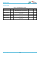


Table Of Contents
- General Description
- Key Features
- Applications
- Device Family
- Contents
- 1. References
- 2. Block Diagram
- 3. Terminal Configuration and Functions
- 4. Specifications
- 5. Detailed Description
- 6. Applications, Implementation, and Layout
- 7. Mechanical Specifications
- 8. Ordering Information
- 9. Revision History
- 10. Regulatory

BDE Dual-Band WiFi MCU Module
Datasheet
info@bdecomm.com
BDE Technology Inc.
BDE-WF3235
10 / 77
Pin #
Pin Name
Type
(1)
Description
13
FLASH_SPI_MISO
I
External serial flash programming: SPI data in
14
FLASH_SPI_nCS_IN
I
External serial flash programming: SPI chip select (active low)
15
FLASH_SPI_CLK
I
External serial flash programming: SPI clock
16
GND
–
Ground
17
FLASH_SPI_MOSI
O
External serial flash programming: SPI data out
18
JTAG_TDO
I/O
JTAG TDO output. Leave unconnected if not used on product
(1)
19
GPIO28
I/O
GPIO
(2)
20
NC
–
No Connect
21
JTAG_TCK
I/O
JTAG TCK input. Leave unconnected if not used on product.
(2)
An internal
100-kΩ pulldown resistor is tied to this pin.
22
JTAG_TMS
I/O
JTAG TMS input. Leave unconnected if not used on product.
(2)
23
SOP2
–
An internal 100-kΩ pulldown resistor is tied to this SOP pin. An external 10-kΩ
resistor is required to pull this pin high. See Section 5.11 for SOP[2:0]
configuration modes.
24
SOP1
–
An internal 100-kΩ pulldown resistor is tied to this SOP pin. An external 10-kΩ
resistor is required to pull this pin high. See Section 5.11 for SOP[2:0]
configuration modes.
25
GND
–
Ground
26
GND
–
Ground
27
GND
–
Ground
28
GND
–
Ground
29
GND
–
Ground
30
GND
–
Ground
31
NC
–
No Connect
32
GND
–
Ground
33
NC/RF_ABG
–
No Connect/RF_ABG pad for BDE-WF3235SN32/BDE-WF3235SFN32
34
SOP0
–
An internal 100-kΩ pulldown resistor is tied to this SOP pin. An external 10-kΩ
resistor is required to pull this pin high. See Section 5.11 for SOP[2:0]
configuration modes.
35
nRESET
I
There is an internal, 100-kΩ pullup resistor option from the nRESET
pin to VBAT_RESET. Note: VBAT_RESET is not connected to VBAT1
or VBAT2 within the module. The following connection schemes are
recommended:
• Connect nRESET to a switch, external controller, or host, only if
nRESET will be in a defined state under all operating conditions.
Leave VBAT_RESET unconnected to save power.
• If nRESET cannot be in a defined state under all operating conditions,
connect VBAT_RESET to the main module power supply (VBAT1 and
VBAT2). Due to the internal pullup resistor a leakage current of 3.3 V /
100 kΩ is expected.
36
VBAT_RESET
–
37
VBAT1
Power
Power supply for the module, must be connected to battery (2.3 V to
3.6 V)
38
GND
–
Ground
39
NC
–
No Connect
40
VBAT2
Power
Power supply for the module, must be connected to battery (2.3 V to
3.6 V)
41
NC
–
No Connect
42
GPIO30
I/O
GPIO
(2)