
Data Sheet
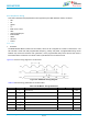

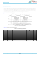
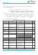

Table Of Contents
- General Description
- Key Features
- Applications
- Device Family
- Contents
- 1. References
- 2. Block Diagram
- 3. Terminal Configuration and Functions
- 4. Specifications
- 5. Detailed Description
- 6. Applications, Implementation, and Layout
- 7. Mechanical Specifications
- 8. Ordering Information
- 9. Revision History
- 10. Regulatory

info@bdecomm.com
BDE Technology Inc.
BDE-WF3235
BDE Dual-Band WiFi MCU Module
Datasheet
Datasheet
49 / 77
4.8.5.7 Camera Parallel Port
The fast camera parallel port interfaces with a variety of external image sensors, stores the image data in a
FIFO, and generates DMA requests. The camera parallel port supports 8 bits.
Figure 4-13 shows the timing diagram for the camera parallel port.
Figure 4-13. Camera Parallel Port Timing Diagram
Table 4-18 lists the timing parameters for the camera parallel port.
Table 4-18. Camera Parallel Port Timing Parameters
ITEM
NAME
DESCRIPTION
MIN
MAX
UNIT
pCLK
Clock frequency
2
MHz
T2
T
clk
Clock period
1/pCLK
ns
T3
t
LP
Clock low period
T
clk
/2
ns
T4
t
HT
Clock high period
T
clk
/2
ns
T6
t
IS
RX data setup time
2
ns
T7
t
IH
RX data hold time
2
ns
4.8.5.8 UART
The BDE-WF3235 MCU includes two UARTs with the following features:
• Programmable baud-rate generator allowing speeds up to 3 Mbps
• Separate 16-bit × 8-bit TX and RX FIFOs to reduce CPU interrupt service loading
• Programmable FIFO length, including a 1-byte-deep operation providing conventional double-buffered
interface
• FIFO trigger levels of 1/8, 1/4, 1/2, 3/4, and 7/8
• Standard asynchronous communication bits for start, stop, and parity
• Generation and detection of line-breaks
• Fully programmable serial interface characteristics:
– 5, 6, 7, or 8 data bits
– Generation and detection of even, odd, stick, or no-parity bits
– Generation of 1 or 2 stop-bits
• RTS and CTS hardware flow support
• Standard FIFO-level and end-of-transmission interrupts
• Efficient transfers using µDMA:
– Separate channels for transmit and receive
– Receive single request asserted when data is in the FIFO; burst request asserted at programmed
FIFO level
– Transmit single request asserted when there is space in the FIFO; burst request asserted at
programmed FIFO level
• System clock is used to generate the baud clock.