
Data Sheet

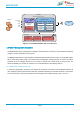
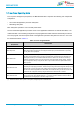
Table Of Contents
- General Description
- Key Features
- Applications
- Device Family
- Contents
- 1. References
- 2. Block Diagram
- 3. Terminal Configuration and Functions
- 4. Specifications
- 5. Detailed Description
- 6. Applications, Implementation, and Layout
- 7. Mechanical Specifications
- 8. Ordering Information
- 9. Revision History
- 10. Regulatory

info@bdecomm.com
BDE Technology Inc.
BDE-WF3235
BDE Dual-Band WiFi MCU Module
Datasheet
Datasheet
51 / 77
4.8.5.11 Timers
Programmable timers can be used to count or time external events that drive the timer input pins. The general-
purpose timer module (GPTM) of the BDE-WF3235 MCU contains 16- or 32-bit GPTM blocks. Each 16- or 32-
bit GPTM block provides two 16-bit timers or counters (referred to as Timer A and Timer B) that can be configured
to operate independently as timers or event counters, or they can be concatenated to operate as one 32-bit timer.
Timers can also be used to trigger µDMA transfers.
The GPTM contains four 16- or 32-bit GPTM blocks with the following functional options:
• Operating modes:
– 16- or 32-bit programmable one-shot timer
– 16- or 32-bit programmable periodic timer
– 16-bit general-purpose timer with an 8-bit prescaler
– 16-bit input-edge count- or time-capture modes with an 8-bit prescaler
– 16-bit PWM mode with an 8-bit prescaler and software-programmable output inversion of the PWM
signal
• Counts up or counts down
• Sixteen 16- or 32-bit capture compare pins (CCP)
• User-enabled stalling when the microcontroller asserts CPU Halt flag during debug
• Ability to determine the elapsed time between the assertion of the timer interrupt and entry into the
interrupt service routine
• Efficient transfers using micro direct memory access controller (µDMA):
– Dedicated channel for each timer
– Burst request generated on timer interrupt
• Runs from system clock (80 MHz)