
Instruction manual

NOTE: Read the entire instruction manual before starting the installation.
This symbol → indicates a change since the last issue.
SAFETY CONSIDERATIONS
Improper installation, adjustment, alteration, service, maintenance, or use can cause explosion, fire, electrical shock, or other conditions which may
cause personal injury or property damage. Consult a qualified installer, service agency, or your distributor or branch for information or assistance.
The qualified installer or agency must use factory-authorized kits or accessories when modifying this product. Refer to the individual instructions
packaged with kits or accessories when installing.
Follow all safety codes. Wear safety glasses and work gloves. Use quenching cloth for brazing operations. Have fire extinguisher available. Read
these instructions thoroughly and follow all warnings or cautions attached to the unit. Consult local building codes and National Electrical Code
(NEC) for special requirements.
Recognize safety information. This is the safety-alert symbol
. When you see this symbol on the unit and in instructions manuals, be alert to
the potential for personal injury.
Understand the signal words DANGER, WARNING, CAUTION, and NOTE. These words are used with the safety-alert symbol. DANGER
identifies the most serious hazards which will result in severe personal injury or death. WARNING signifies hazards which could result in personal
injury or death. CAUTION is used to identify unsafe practices which would result in minor personal injury or product and property damage. NOTE
is used to highlight suggestions which will result in enhanced installation, reliability, or operation.
WARNING: Before installing or servicing unit, always turn off all power to unit. There may be more than 1 disconnect
switch. Turn off accessory heater power if applicable. Electrical shock can cause personal injury or death.
INTRODUCTION
Models FA4A, FB4A, FC4B, and FH4A are designed for flexibility and can be used for upflow, horizontal, or downflow (kit required and
manufactured and mobile home) applications. These units are available for systems of 24,000 through 60,000 Btuh nominal cooling capacity.
Factory authorized electric heater packages are available in sizes 3 through 30kw. See Product Data Literature for available accessory kits.
HEATER PACKAGES
This unit may or may not be equipped with an electric heater package. For units not equipped with factory installed heat, a factory approved, field
installed UL listed heater package is available from your equipment supplier. See unit rating plate for a list of factory approved heaters. Heaters
that are not factory approved could cause damage which would not be covered under the equipment warranty. If fan coil contains a factory installed
heater package, minimum circuit ampacity (MCA) and maximum fuse/breaker may be different than units with a same size field installed accessory
heater. The difference is not an error and is due to calculation difference per UL guidelines.
INSTALLATION
PROCEDURE 1—MOUNT UNIT
Unit can stand or lie on floor, or hang from ceiling or wall. Allow space for wiring, piping, and servicing unit.
IMPORTANT: When unit is installed over a finished ceiling and/or living area, building codes may require a field-supplied secondary condensate
pan to be installed under the entire unit. Some localities may allow as an alternative, the running of a separate, secondary condensate line. Consult
local codes for additional restrictions or precautions.
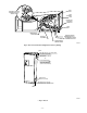
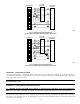
A. Upflow Installation
If return air is to be ducted through a floor, set unit on floor over opening and use 1/8- to 1/4-in. thick fireproof resilient gasket between duct,
unit, and floor.
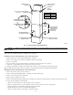
Side return is a field option on slope coil models. Cut opening per dimensions. (See Fig. 1.) A field-supplied bottom closure is required.
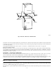
B. Downflow Installation
In this application, field conversion of the evaporator coil is required using accessory downflow kit along with an accessory base kit. See
installation instructions packaged with accessory kit. See Product Data for kit part numbers.
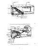
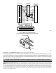
C. Horizontal Installation
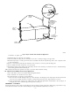
Units must not be installed with access panels facing up or down. The FH4A003 and 004 size units equipped with accessory cooling coils are not
approved for horizontal applications. All other units are factory built for horizontal left installation. (See Fig. 2 and 6.) When suspending unit from
ceiling, dimples in casing indicate suitable location of screws for mounting metal support straps. (See Fig. 2.)
Direct Expansion Fan Coil Units Fan Unit
FA4A, FB4A, FC4B
FH4A
Form: IM-FA4A-11 Cancels: IM-FA4A-10 Printed in U.S.A. 3-02 Catalog No. 63FA-4A6