
User`s guide


5 Installation
1
Introduction
STEP 1 :
STEP 2 :
STEP 3 :
STEP 4 :
STEP 5 :
STEP 6 :
STEP 7 :
STEP 8 :
STEP 9 :
STEP 10:
Page 2:
Page 2:
Page 2:
Page 3:
Page 3:
Page 4:
Page 4:
Page 5:
Page 5:
Page 6:
Introduction
Install DP-Hub
Install ON/OFF/HOLD Switch
Install BodyGuard
Install Door Control Harness(s)
Install Door Mounted Sensor(s)
Install EDPS(s)
Install Home Switch
Door Mounted Safety Side Manual Inhibit (optional)
Install Eagle(s) (optional)
STEP 11:
STEP 12:
STEP 13:
STEP 14:
STEP 15:
STEP 16:
STEP 17:
Page 6:
Page 7:
Page 7:
Page 8:
Page 8:
Page 9:
Page 9:
Install Auxiliary/Push Plate(s) (optional)
Install Photo Beams SBK-30 (optional)
Install Power Harness
Congure BodyGuard III
Check Function Number of Doors on DP-Hub
Perform Door Position System Learn
Perform Walk Test
CONNECTION DIAGRAM:
1 Door Mounted 1
2 Door Mounted 2
3 BodyGuard
4 Eagle 1
5 Eagle 2
6 Power
7 SBK-30 Beams
8 Auxiliary/Push Plate(s)
9 ON/OFF/HOLD Switch
10 Programming - FUNC (Function)
11 Programming - INCR (Increment)
12 Learn/Home/Tracking LEDs
13 Safety/Stall/Activation LEDs
14 Door Control 2
15 Door Control 1
16 Door Mounted 2 Manual Inhibit
17 Door Mounted 1 Manual Inhibit
INSTALLATION HARNESSES:
BEA P/N:
20.5078.02
20.5082
20.5083
20.5222
20.5215.02
20.5096
20.5095
DESCRIPTION:
ON/OFF/HOLD Switch Harness
BodyGuard Harness
BodyGuard Y Harness (optional for dual egress pair)
Door Control Harness
Door Mounted/EDPS Harness
Eagle Harness
Power Harness
Page 2 of 16 75.5652.03 20130617
2
Install DP-Hub
1. Install the DP-Hub in an accessible location inside the door header using supplied velcro strips. Allow adequate space to easily see the DP-Hub
display, to access the push buttons and to access all connectors.
3
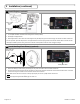
Install ON/OFF/HOLD Switch
1. Install ON/OFF/HOLD Switch in desired location. Ensure the
location is easily accessible.
2. Route wiring harness (20.5078.02) from ON/OFF/HOLD Switch to DP-Hub
and plug into DP-Hub at location marked ‘SW’.
NOTE: When changing the state of the ON/OFF/HOLD switch, the door will not open or close if the Bodyguard is in detection.
NOTE: If the door control also has an ON/OFF/HOLD switch, make sure to jump it to the ON position and use the BEA ON/OFF/HOLD Switch.
WHITE
BLACK
RED
Switch Cable
Route to ‘SW’
ON/OFF/HOLD Switch
10
9
8
7
6
5
4
3
2
1
11
12
13
141517
16
When upgrading from an LO-Linx make sure that
the wire colors are in the order shown above, as
the LO-Linx was packaged with a different model
ON/OFF/HOLD Switch.