
User's Manual


Page 2 of 4 75.5858.02 900 MHZ INDUSTRIAL 20160205
• The device should not be used for purposes other than its intended use. All other uses cannot be guaranteed by
the manufacturer of this device.
• The installer of the door system is responsible for carrying out a risk assessment and installing this device and the
door system in compliance with applicable national and international regulations and standards on door safety.
• The manufacturer of this device cannot be held responsible for incorrect installations or inappropriate adjustments
of this device.
PRECAUTIONS
q Shut off all power going to header before attempting any wiring procedures.
q Maintain a clean & safe environment when working in public areas.
q Constantly be aware of pedestrian traffic around the door area.
q Always stop pedestrian traffic through the doorway when performing tests that may result in unexpected reactions
by the door.
q ESD (electrostatic discharge): Circuit boards are vulnerable to damage by electrostatic discharge. Before handling
any board ensure you dissipate your body’s ESD charge.
q Always check placement of all wiring before powering up to ensure that moving door parts will not catch any wires
and cause damage to equipment.
q Ensure compliance with all applicable safety standards (i.e. ANSI A156.10) upon completion of installation.
q DO NOT attempt any internal repair of the components. All repairs and/or component replacements must be
performed by BEA, Inc. Unauthorized disassembly or repair:
1. May jeopardize personal safety and may expose one to the risk of electrical shock.
2. May adversely affect the safe and reliable performance of the product resulting in a voided warranty.
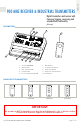
Hand Held Configuration
INSTALLATION
Wiring
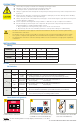
TERMINAL: 1 2 3 4 5
LABEL: 12-24 V 12-24 V COM NO NC
WIRE COLOR: red black white green yellow
SIGNAL: + voltage - voltage common normally-open normallyclosed
DESCRIPTION: power relay contacts
SETUP
DIP Switches
DIP STATUS FUNCTION DESCRIPTION
1
PUL Pulse Relay pressing transmitter activates and holds relay according to DIP 2 and 3
TOG
Toggle
Relay
pressing transmitter once activates and holds relay indefinitely
pressing transmitter again deactivates relay immediately (no hold)
2
(PUL only)
0.5s
0.5 second
hold time
relay remains active for 0.5 seconds after transmitter is...
pressed [STD] released [EH]
10s
10 second
hold time
relay remains active for 10 seconds after transmitter is...
pressed [STD] released [EH]
3
STD
standard
hold
relay acts according to DIP 1 and 2
(does not matter if transmitter is pressed/released or pressed/held)
EH
extended
hold
relay remains active as long as transmitter is pressed and held
once released, relay acts according to DIP 1 and 2
1 2 3
ON
1 2 3
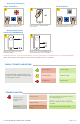
Set DIP switches as desired. Press transmitter twice (blue LED
on receiver will illuminate).
Press and release desired learn button
(red LED on receiver will illuminate)
1
.
NOTES:
1
If Learn w/ Delay button is used, adjust potentiometer (1 s to 30 s).