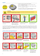
EN A E B L E S O A C C R D A A E W I T H 50 186 DIN C E R L AU BT W I T H E C N A N H H N Z I E RUNG FI TI E N N C EN E 05 160 R Z N E R L AU BT Z I E RUNG FI TI Z R C E A B L E S O A C C R D A ® LZR -P110 LASER SCANNER FOR PEDESTRIAN DOORS User’s Guide for product version 0600 and higher See product label for serial number SLIDING SWINGING REVOLVING 1
SAFETY The device contains IR and visible laser diodes. IR laser: wavelength 905nm; max. output pulse power 75W (Class 1 according to IEC 60825-1) Visible laser: wavelength 650nm; max. output CW power 3mW (Class 3R according to IEC 60825-1) The visible laser beams are inactive during normal functioning. The installer can activate the visible lasers if needed. CAUTION! Use of controls, adjustments or performance of procedures other than those specified herein may result in hazardous radiation exposure.
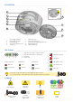
DESCRIPTION 1 2 3 4 5 7 8 6 9 10 1. 2. 3. 4. 5. 6. 7. 8. 9. 10. laser sweep emission laser sweep reception LED-signals (4) screws for position lock (2) connector protection cover visible laser beams (3) notches for tilt angle adjustment (2) adjustable bracket cable conduits (4) LED-SIGNAL 1 3 2 4 DETECTION LEDs detection no detection 1. 2. 3. 4.
HOW TO USE THE REMOTE CONTROL 4 hours after last use, the sensor locks the access to the remote control session. Cut and restore power supply. The remote control session is accessible again during 4 hours. After unlocking, the red LED flashes and the sensor can be adjusted by remote control. If the red LED flashes quickly after unlocking, you need to enter an access code from 1 to 4 digits. 4h To end an adjustment session, always lock the sensor.
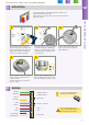
Please go to the section that fits your door application: 1 P. 5 P. 9 P. 13 SLIDING SWINGING REVOLVING MOUNTING 1 2 10 cm 3 45° Use the mounting template to position the sensor correctly. The grey area indicates the detection range. Drill 4 holes and make a hole for the cable if possible. 4 45° Pass the cable +/- 10 cm though the cable opening. If drilling an opening is not possible, use the cable conduits on the back side of the bracket.
3 POSITIONING Unlock the sensor and activate the visible laser beams in order to position the curtains parallell to the door. The visible laser beams indicate approximately the postion of the curtain closest to the door. 90° They stay activated for 15 minutes or can be turned off the same way they were activated. 0° 45° 1 2 door frame door frame door frame 5 cm visible laser beam Adjust the lateral position of the detection field.
5 SAFETY FIELD CONFIGURATION 5.1 SAFETY FIELD TEACH-IN Launch a teach-in after changing the sensor position or when new objects are added to or changed in the detection zone. The sensor will learn its surroundings and adapt the detection field shape to these. Objects in the detection field will be cut out. During teach-in, the detection field should be free of snow buildups, heavy rain, snowfall, fog or other moving objects. 3s max.
6 OPTIONAL CONFIGURATION 6.1 VIRTUAL PUSH BUTTON TEACH-IN (VPB) Make sure the white and yellow wires are connected to the corresponding inputs before configuring the virtual push buttons. Install 1 or 2 virtual push buttons to open the door «manually». 1 Apply the vitual push button sticker(s) within the optional field. 2 Launch a VPB teach-in to configure the detection zone(s). When the red LED flashes very slowly after 3 seconds, hold your hand in front of the sticker to learn the detection zone.
Please go to the section that fits your door application: 1 P. 5 P. 9 P. 13 SLIDING SWINGING REVOLVING MOUNTING 1 2 10 cm 45° Use the mounting template to position the sensor correctly. The grey area indicates the detection range. Drill 4 holes and make a hole for the cable if possible. 3 45° Pass the cable +/- 10 cm though the cable opening. If drilling an opening is not possible, use the cable conduits on the back side of the bracket.
3 POSITIONING Unlock the sensor and activate the visible laser beams in order to position the curtains parallell to the door. 90° The visible laser beams indicate approximately the postion of the curtain closest to the door. They stay activated for 15 minutes or can be turned off the same way they were activated. 45° 0° 1 2 door axis door axis door axis 10 cm visible laser beam Adjust the lateral position of the detection field.
5 SAFETY FIELD CONFIGURATION 5.1 SAFETY FIELD TEACH-IN Launch a teach-in after changing the sensor position or when new objects are added to or changed in the detection zone. The sensor will learn its surroundings and adapt the detection field shape to these. Objects in the detection field will be cut out. During teach-in, the detection field should be free of snow buildups, heavy rain, snowfall, fog or other moving objects. 3s max.
6 OPTIONAL CONFIGURATION 6.1 ACTIVATING/ DEACTIVATING THE DETECTION CURTAINS Depending on the needed field depth, activate or deactivate the detection curtains. X X X X λ1 λ2 λ3 λ4 All curtains are active curtain is inactive curtain is active λ1 λ2 λ3 λ4 Ex: λ1 + λ 2 are active λ 3 + λ4 are inactive The distance between the curtains depends on the mounting height and side. When mounted on the left, the distance between λ1 and λ4 is approximately 10 cm for every meter (mounting height).
Please go to the section that fits your door application: 1 P. 5 P. 9 P. 13 SLIDING SWINGING REVOLVING MOUNTING 1 2 10 cm 3 45° Use the mounting template to position the sensor correctly. The grey area indicates the detection range. Drill 4 holes and make a hole for the cable if possible. 4 45° Pass the cable +/- 10 cm though the cable opening. If drilling an opening is not possible, use the cable conduits on the back side of the bracket.
3 POSITIONING Unlock the sensor and activate the visible laser beams in order to position the curtains parallell to the door. 90° The visible laser beams indicate approximately the postion of the curtain closest to the door. They stay activated for 15 minutes or can be turned off the same way they were activated. 1 45° 0° 2 door axis door axis door axis 10 cm visible laser beam Adjust the lateral position of the detection field.
5 SAFETY FIELD CONFIGURATION 5.1 SAFETY FIELD TEACH-IN Launch a teach-in after changing the sensor position or when new objects are added to or changed in the detection zone. The sensor will learn its surroundings and adapt the detection field shape to these. Objects in the detection field will be cut out. During teach-in, the detection field should be free of snow buildups, fog or other moving objects. 3s max.
6 OPTIONAL CONFIGURATION (RELAY 1) 6.1 SLOW-DOWN FUNCTION The optional field can be used to slow down the door.
SAFETY FIELD DIMENSIONS OPTIONAL OTHER REMOTE CONTROL CONFIGURATIONS R1 same as safety field 0.5 m R1 no field 0.5 m R2 no field 0.5 m In order to configure the field dimensions of the optional field (relay 1), you have to cancel the virtual push button function by launching a new VPB teachin without any movement in the detection field. 5.0 m 5.0 m 5.0 m R2 0.5 m 5.
TROUBLESHOOTING There is no power. 1 Check cable and connexion. The polarity of the power supply is inverted. 1 Check the polarity of the power supply. All LEDs have been deactivated by remote control. 1 Activate the LEDs by remote control. Only the blue LED is on. The test input is not connected. 1 Check wiring. The RED and BLUE cable have to be connected to the test input or the power supply. The detection LED remains green. The detection field is too small or deactivated.
TECHNICAL SPECIFICATIONS Technology: laser scanner, time-of-flight measurement Detection mode: motion and presence Max. detection range: 5.0 m x 5.0 m Uncovered zone: 5 - 25 cm (adjustable) Remission factor: >2% Angular resolution: 0,3516 ° Min. detected object size (typ.): 2,1 cm @ 3 m ; 3,5 cm @ 5 m (in proportion to object distance) 700 mm x 300 mm x 200 mm (testbody CA according to EN 16005/DIN 18650) Testbody: Emission characteristics: wavelength 905 nm; max.
PLEASE KEEP FOR FURTHER USE DESIGNED FOR COLOUR PRINTING ©BEA | Original instructions | 42.7773 / V1 - 01.13 BEA SA | LIEGE SCIENCE PARK | ALLÉE DES NOISETIERS 5 - 4031 ANGLEUR [BELGIUM] | T +32 4 361 65 65 | F +32 4 361 28 58 | INFO@BEA.BE | WWW.BEA.BE BEA hereby declares that the LZR ® -P110 is in conformity with the basic requirements and the other relevant provisions of the directives 2006/95/EC, 2002/95/EC, 2004/108/EC and 2006/42/EC.