
Install Instructions


TWIN-FLO
ROOM T’STAT
12
115 V LINE
CIRCULATOR
ZONE VALVE
W/AUX. SW.
TRANS
LOW VOLT
115/ 24V
MIN
MAX
T-STAT
(NEUTRAL)L2
115 /1/60
LINE IN
L1
BLUE
(HOT)
SPDT
2
1
3
BLOWER
WHT
MOTOR
BLK
RED
CAT-68254-A
BLUE
OFF
WIRING DIAGRAM C
WIRING DIAGRAM A WIRING DIAGRAM B
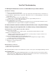
ELECTRICAL CONNECTIONS
CAUTION! For Supply Connections, use wires suitable for at least 194°F (90°C).
3.
A shaded pole motor is used to drive the Twin-Flo III blower on 115 -120 V. 60 hz. Since current drain is very
small, wiring codes for short circuit protection only will apply. The motor is connected in series with a normally
open aquastat in contact with the heating element. Therefore, the blower runs only when unit is suffi ciently
hot and the switch is in the "min" or "max" position (not "off"). A ground screw is supplied with all units.
Electrical connections are to be made to all units following the diagrams below. Choose the diagram that best
suits your application.
Since the blower runs on all Twin-Flo III models only when the system circulator pumps hot water through the
unit, simply connect it to the 115 V line. The blower then starts after a short warm-up, and stops a few min-
utes after the circulator shuts off (see diagram A).
Adding a line voltage type room thermostat will permit the setting of a maximum room temperature (see dia-
gram B). This 'T' stat will only operate the kickspace unit. If the circuit or system circulator is not running, the
kickspace heater will not operate.
All electrical connections must conform to local and national codes.
Connection through a circulator or zone auxiliary switch may also be used to permit instant shutdown of the
blower as the circulator stops (see diagram #3).
K-42
K-84
K-120
1 GALLON
2 GALLONS
3 GALLONS
.50
.50
.74
.17'
.8'
1.2'
53
103
127
30.7
30.7
66.8
.22'
.95'
1.5'
AMPUNIT K42CFM (HIGH SPEED)
MOTOR INFORMATION FRICTION LOSS (HEAD)
3200
3200
3200
.43'
1.45'
2.97'
.034
.034
.068
115
115
115
WATT K84VOLTAGERPM K120HP
MIN
MAX
T-STAT
(NEUTRAL)L2
(GND)
GREEN SCREW
115/1/60
LINE IN
L1
BLUE
(HOT)
SPDT
2
1
3
BLOWER
WHT
MOTOR
BLK
RED
115V LINE
CAT-68252-A
BLUE
OFF
LINE VOLT
ROOM T’STAT
RW
MIN
MAX
T-STAT
(NEUTRAL)L2
(GND)
GREEN SCREW
115/1/60
LINE IN
L1
BLUE
(HOT)
SPDT
2
1
3
BLOWER
WHT
MOTOR
BLK
RED
115V LINE
CAT-68253-A
BLUE
OFF